

Hub unit with wheel support and bearing ring, and method of manufacturing the hub unit
A hub unit and bearing ring technology, applied in the field of bearing ring components, can solve the problems of increased molding load, reduced output, large excess thickness, etc., and achieve the effect of reduced cutting allowance and low price
- Summary
- Abstract
- Description
- Claims
- Application Information
AI Technical Summary
Problems solved by technology
Method used
Image

Examples
no. 1 example
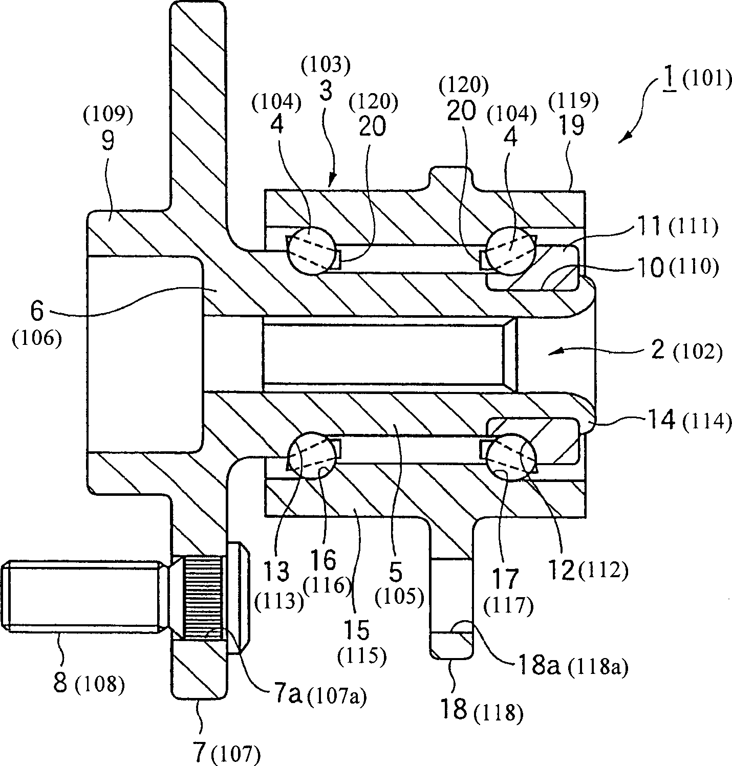
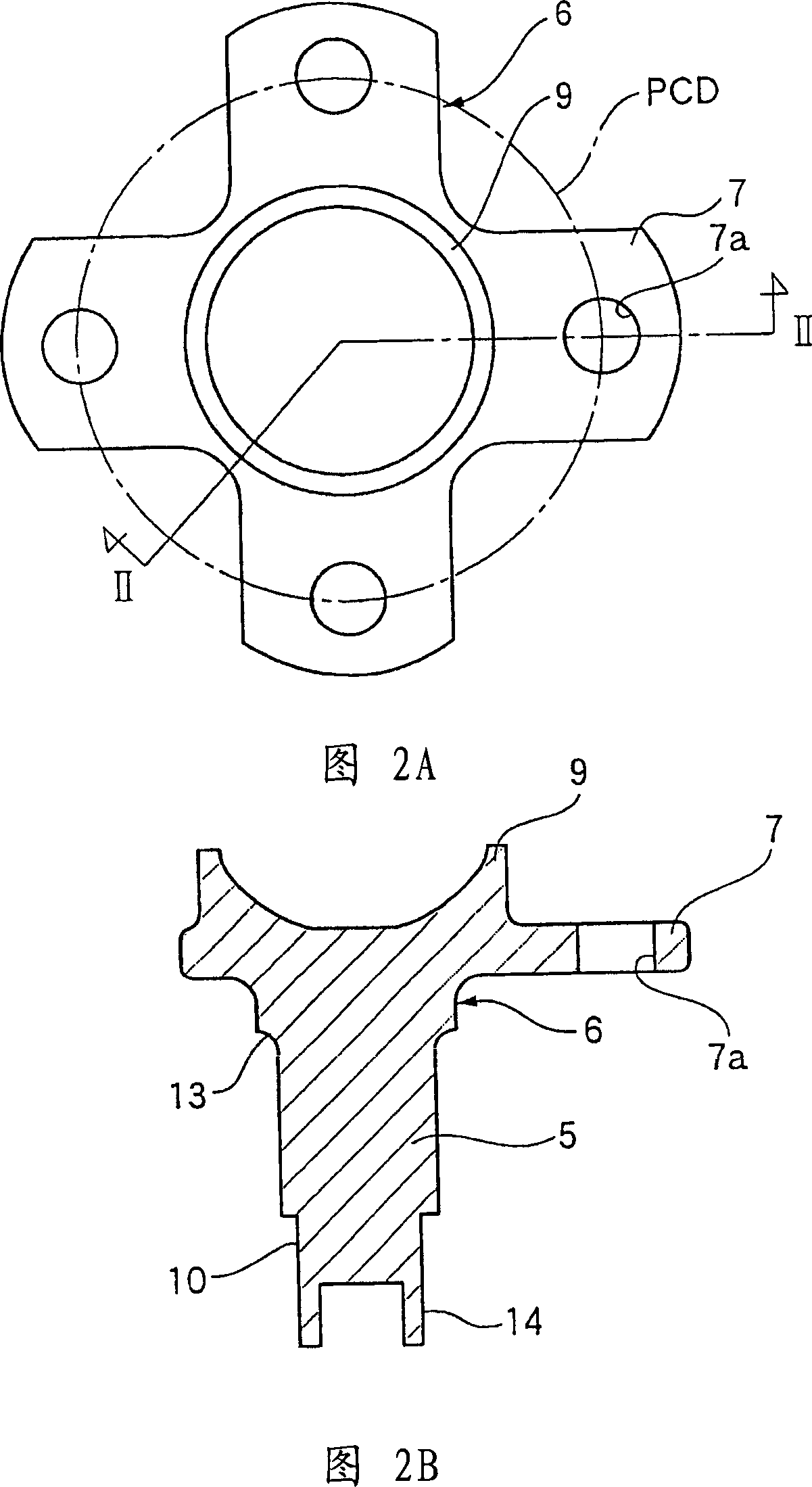
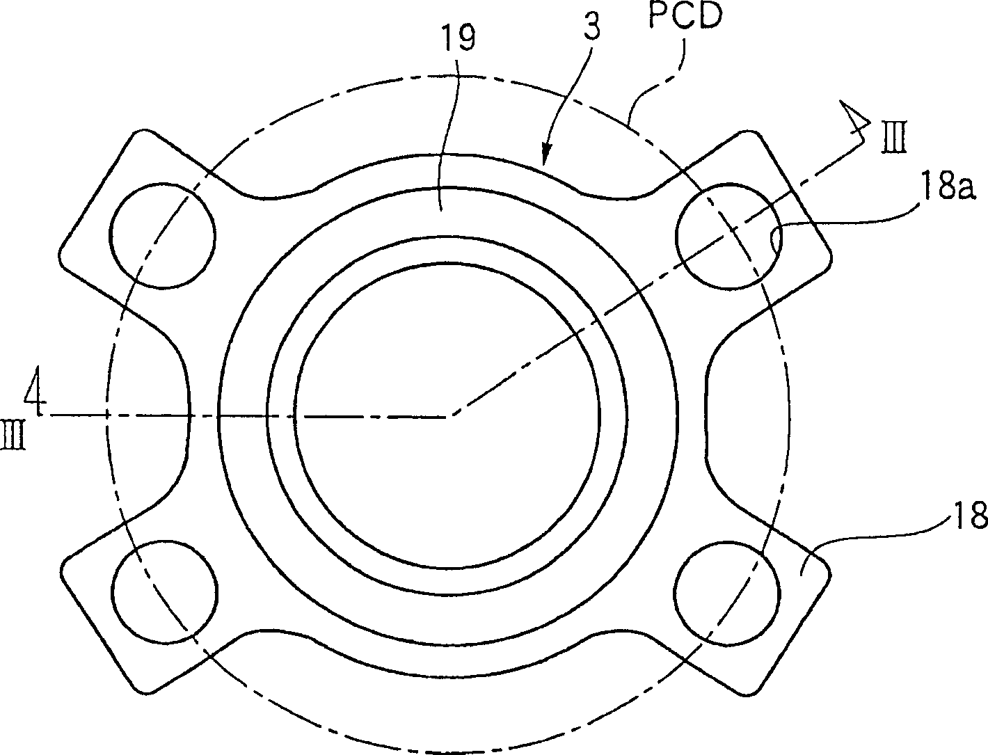
[0077] Such as figure 1 As shown in to 3, a wheel supporting hub unit 1 is used as a driven wheel, and is provided with a bearing unit having a hub (inner member) 2, an outer ring (outer member) 3 serving as a bearing ring member, and a plurality of rolling element 4.
[0078] The hub 2 is provided with a hub wheel 6 comprising a solid shaft part 5 as a bearing ring element. The outer end portion of the hub wheel on its outer peripheral surface (in the vehicle assembled state, the outer end portion in the vehicle width direction (attached figure 1 In the left end part)) place is provided with the wheel fixing flange 7, and this wheel fixing flange 7 constitutes the fixing part that extends in the radially outward direction, and it intersects with the shaft part 5 at right angles. The wheel fixing flange 7 is provided on its outer surface with a plurality of studs 8 inserted therein at substantially equal intervals to thereby fix the wheel, brake rotor, etc. to the wheel fixi...
no. 2 example
[0102] The hub ring 106 of the drive wheel, which is a bearing ring member of the wheel supporting hub unit 101, will be taken as an example, and its manufacturing method will be described. First, as shown in FIG. 10A, a hollow cylindrical shaft portion raw material 130 is subjected to forward extrusion molding to form a shaft portion member 130a of FIG. 10B. Then, the head portion of the shaft portion member 130a is upset to form the shaft portion member 130b shown in FIG. 10C. The shaft portion member 130b is extruded backward by the head portion to form a head portion 132 having a stepped recess 131 forming the inner circumference of the shaft portion 105 and the shape of the positioning cylindrical portion 109 . Then, the head portion 132 is upset so that by using Figure 11 The die 140 shown in , maintains the height of the wheel fixing flange 107 to form the wheel fixing flange 107 .
[0103] The stamper 140 is provided with a lower metal stamper 141, an upper metal st...
no. 3 example
[0110] A method of manufacturing a bearing ring member of a wheel supporting hub unit in a third embodiment of the present invention will now be described in detail with reference to FIG.
[0111] As shown in Figure 12A, the hollow cylindrical shaft part raw material 150 is subjected to forward extrusion molding to form a shaft part element 150a, which has a head part 152, which is provided with a recess 151, which forms the shape of the shaft part shown in Figure 12B. The shaft portion 115 and the inner circumferential shape of the positioning cylindrical portion 119 are positioned. As shown in FIG. 12C , the head portion 152 is then formed into a profiled outer peripheral shape with radial protrusions 153 equal in number to the number of positioning holes 118 a provided in the suspension unit fixing flange 118 . In the upsetting step of FIG. 12D , the shaft portion 115 is then held in the lower die (not shown) at the height of the suspension unit fixing flange 118 by using a...
PUM
 Abstract
Description
Claims
Application Information