Shadow mask

A shadow mask and slit technology, applied in discharge tubes, electrical components, circuits, etc., can solve the problems of not being able to fall on the cathode ray tube, missing electron beams, and luminance drop

Inactive Publication Date: 2006-04-19
DAI NIPPON PRINTING CO LTD
View PDF2 Cites 0 Cited by
  • Summary
  • Abstract
  • Description
  • Claims
  • Application Information

AI Technical Summary

Problems solved by technology

This phenomenon will cause the following problems: the electron beam 7b passing through the slot 2d is partially missing, resulting in a decrea

Method used


Image

  • Shadow mask
  • Shadow mask
  • Shadow mask

Examples


no. 1 Embodiment approach

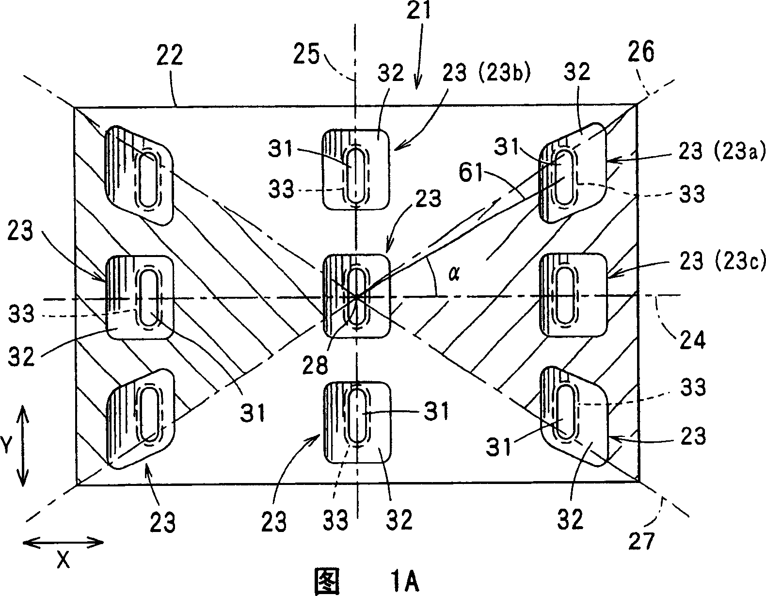
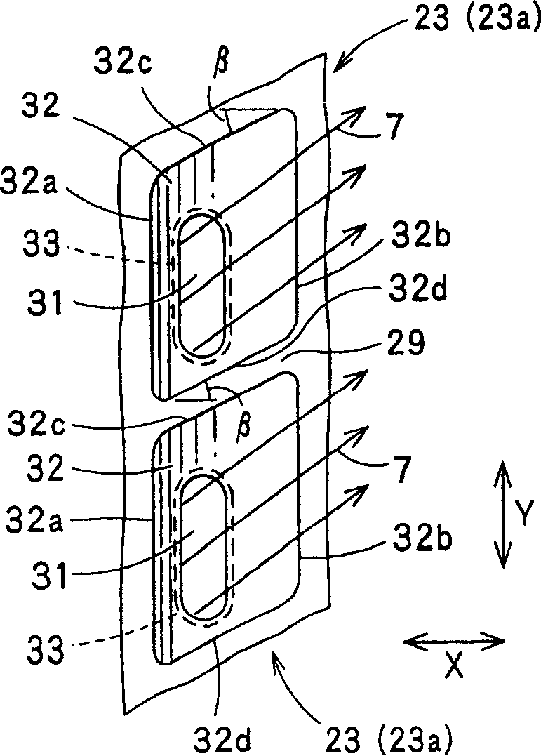
[0033] According to Figure 1A and Figure 1B , the shadow mask according to the first embodiment of the present invention will be described.

[0034] Figure 1A and Figure 1B As shown, the shadow mask 21 of the first embodiment of the present invention has a substantially rectangular shadow mask main body 22, and the shadow mask main body 22 has a plurality of slots 23 (including slots 23a, 23b, 23c), and the slots 23 has a substantially rectangular through hole 31 penetrating in the thickness direction. Here, the through hole 31 of the slit 23 is formed by connecting the front side hole 32 and the back side hole 33 formed by etching a thin metal plate. And, with Figure 4 The solution shown is the same, and a plurality of slots 23 are arranged on the shadow mask main body 22 along the horizontal direction X and the vertical direction Y in plan view. Such a shadow mask 21 is magnetically sealed by being attached to a cathode ray tube, and is used to form a substantially re...

no. 2 Embodiment approach

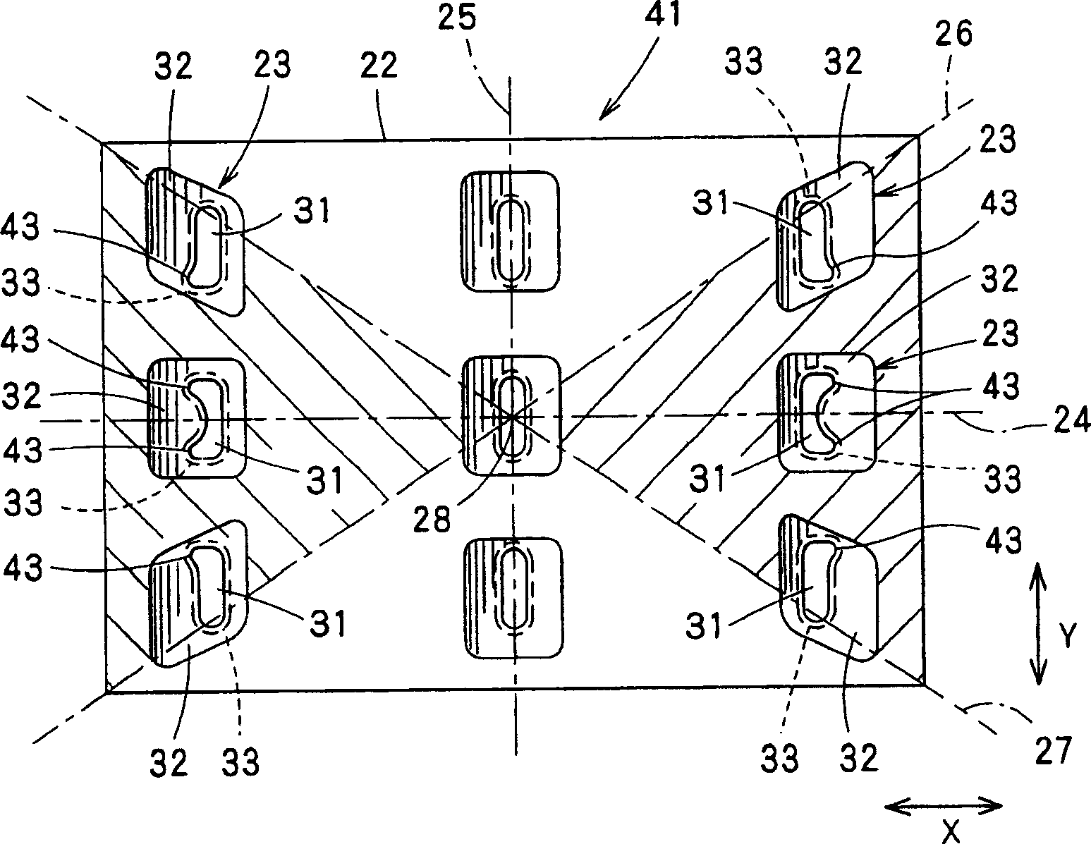
[0051] Next, according to Figure 3A and Figure 3B A shadow mask according to a second embodiment of the present invention will be described. In addition, the second embodiment of the present invention is similar to FIG. 1A and FIG. Figure 1B The first embodiment shown is substantially the same. In Figure 3A and Figure 3B In the second embodiment shown, with respect to Fig. 1A and Figure 1B Components that are the same as in Embodiment 1 shown are denoted by the same reference numerals, and detailed description thereof will be omitted.

[0052] Figure 3A and Figure 3B As shown, the shadow mask 51 of the second embodiment of the present invention has the same Figure 1B The shadow mask 21 shown is similarly constituted, at least in the front side hole portion formed in the area between the horizontal axis 24 and the two diagonal axes 26, 27 of the shadow mask main body 22 (the shaded portion in FIG. 3A ). 32, only the side 32c on the side of the non-horizontal axis 24...


PUM


Abstract

In a shadow mask 21, a large number of slots 23 are made in a mask body 22 in the horizontal direction X and in the vertical direction Y. Each slot 23 has a roughly rectangular backside opening 33, a roughly rectangular front-side opening 32, and a through-hole 31 that connects these two openings 33, 32. Of the multiple slots 23 made in the mask body 22, the slots 23 situated at least in those areas of the mask body 22 that are surrounded by a horizontal axis 24 and two diagonal axes 26, 27 that pass through the center point 28 of the mask body 22 have such front-side openings 32 that a pair of the upper and lower short sides 32c, 32d of the rectangular outline of the front-side opening 32 of each slot 23 are inclined, relative to the horizontal axis 24, along the radiate line 61 radiating from the center point 28 of the mask body 22 toward the slot 23. The angle [beta] of inclination of the short sides 32c, 32d is preferably in the range of +- 10 DEG , where +- is the angle [alpha] between the radiate line 61 radiating from the center point 28 of the mask body toward the slot 23 and the horizontal axis 24.

Description

technical field [0001] The present invention relates to a shadow mask for forming a substantially rectangular electron beam spot on a fluorescent surface of a color cathode ray tube. Background technique [0002] Such as Figure 8 As shown, the shadow mask 1 is used so as to be placed opposite to the fluorescent surface 102 of the color cathode ray tube 101 . In the color cathode ray tube 101, the electron beam 105 emitted from the electron gun 103 and deflected by the magnetic field of the deflection yoke 104 passes through the shadow mask 1 and lands on a predetermined position on the fluorescent surface 102 accurately. [0003] Here, the shadow mask 1 will be described in detail. Figure 4 It is a schematic plan view for explaining the positional relationship of the slits formed in various parts of the shadow mask 1 . Such as Figure 4 As shown, the shadow mask 1 has a substantially rectangular shadow mask main body 1a, and on the shadow mask main body 1a, there are su...

Claims


Application Information

Patent Timeline
IPC IPC(8): H01J29/07
CPCH01J29/076H01J2229/0755H01J29/07
Inventor 秀岛启文冈宏树
Owner DAI NIPPON PRINTING CO LTD
Why Eureka
Try Eureka