Image reading device and method of scaling up or down image to be read

An image reading device and magnification change technology, applied in image communication, electrical components, etc., can solve the problems of increasing the amount of light source light, S/N deterioration, output reduction, etc., and achieve the effect of not increasing the number of read pixels and suppressing costs

Inactive Publication Date: 2006-04-19
NEC CORP
View PDF1 Cites 17 Cited by
  • Summary
  • Abstract
  • Description
  • Claims
  • Application Information

AI Technical Summary

Problems solved by technology

[0004] However, in order to obtain high-definition image data, no matter which method, the number of read pixels per unit length must be increased
[0005] By increasing the number of pixels, the area per pixel becomes smaller, the output decreases, and the S / N ratio deteriorates.
Therefore, the amount of light from the light source must be increased, or the pupil diameter of the lens must be increased, or the reading speed must be reduced.
[0006] In addition, due to the increase in the number of pixels, there are problems in that the data volume of the entire image becomes large, the calculation amount required for image processing and the necessary storage capacity also increase, processing time is consumed, and cost increases.
[0010] The problem to be solved is that in the above-mentioned prior art, when the optical system is moved, since the reflector etc. are moved in parallel along the optical axis, the magnification can only be changed within a relatively narrow range, and the fineness cannot be sufficiently improved. degree and image quality

Method used


Image

  • Image reading device and method of scaling up or down image to be read
  • Image reading device and method of scaling up or down image to be read
  • Image reading device and method of scaling up or down image to be read

Examples


Embodiment 1

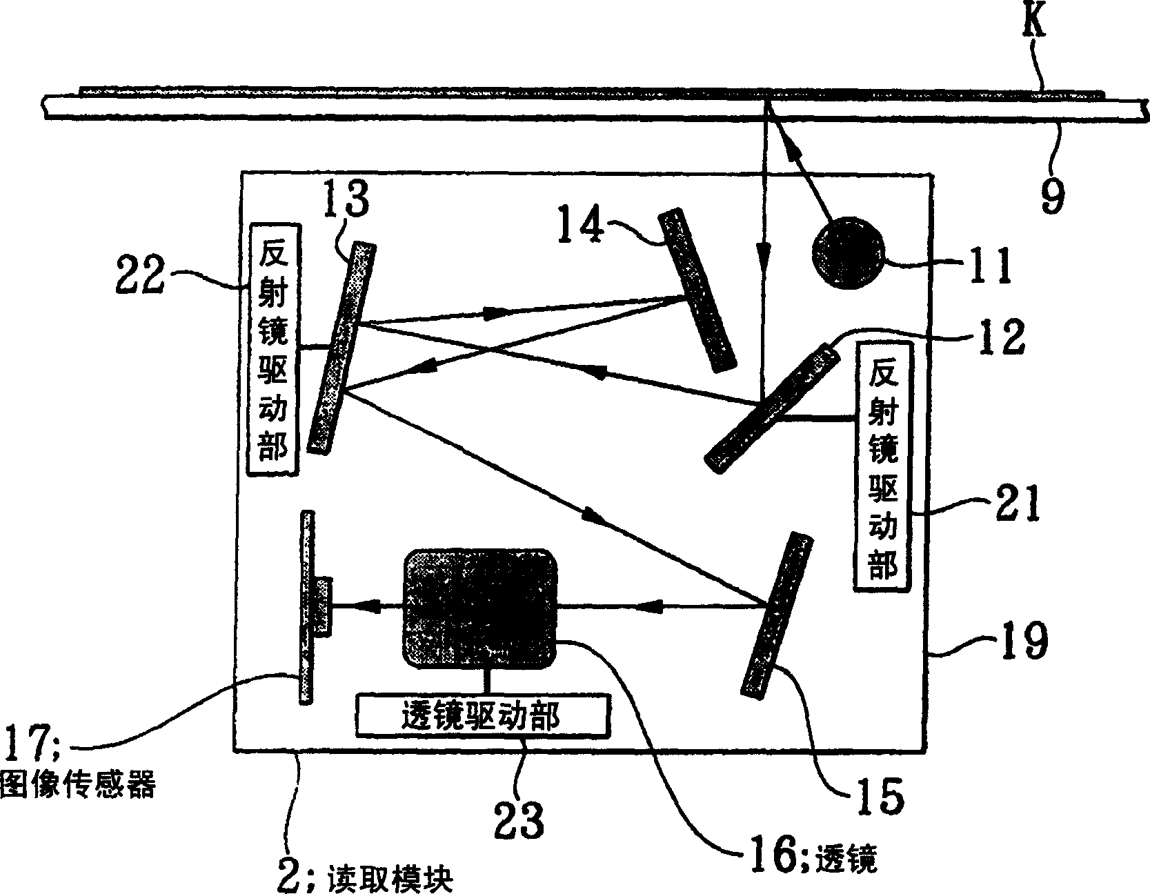
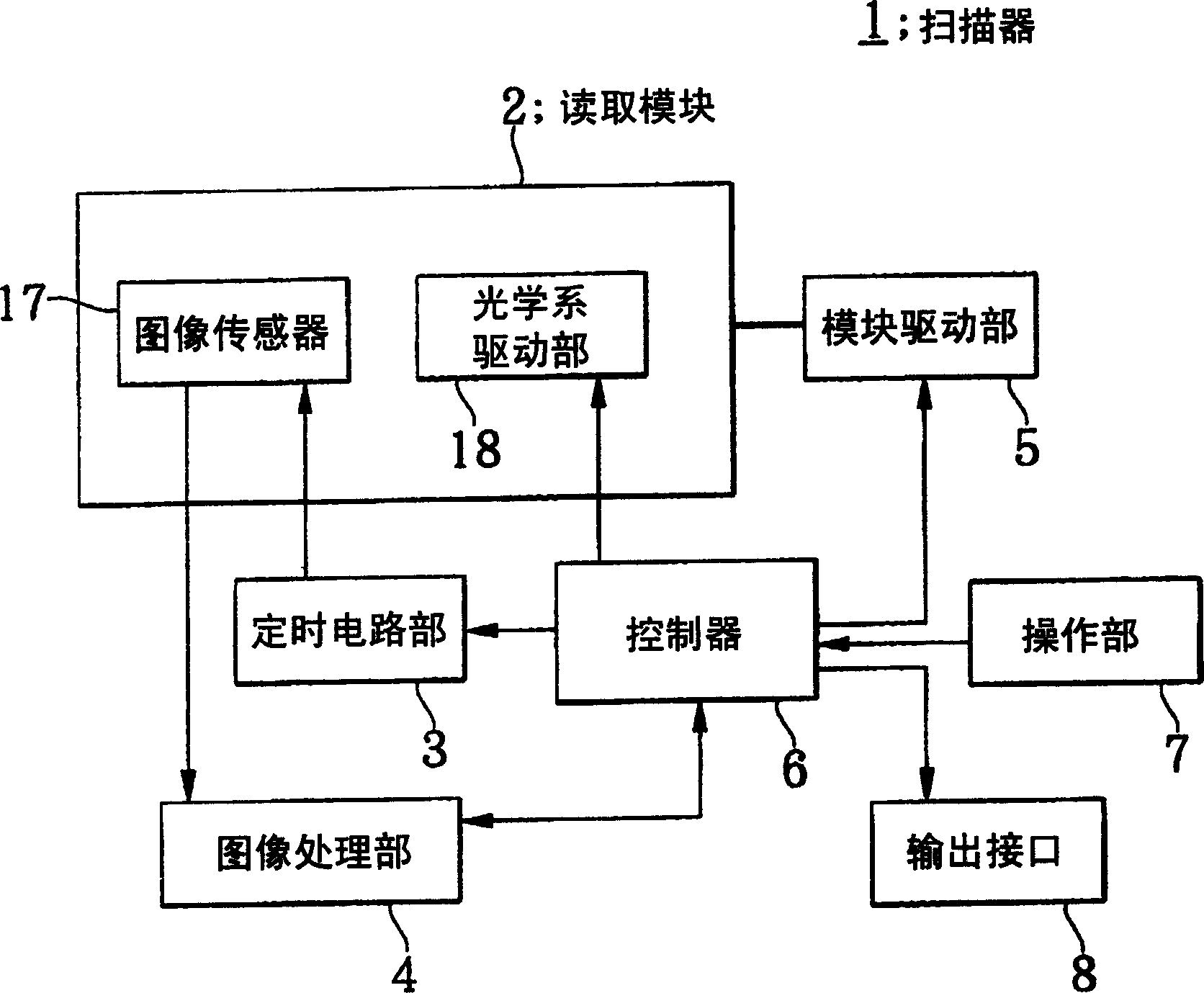
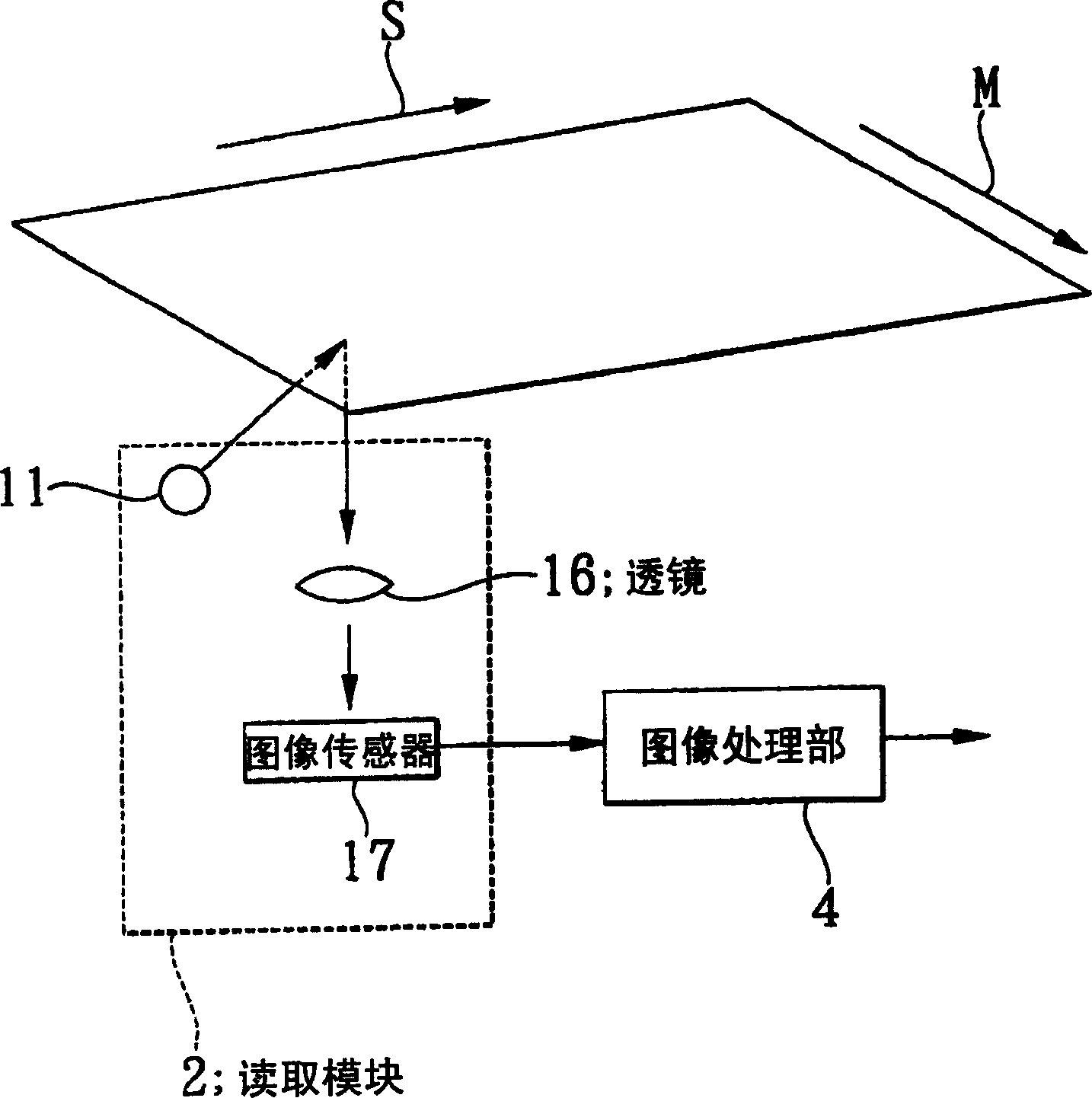
[0039] figure 1 It is a diagram schematically showing the configuration of a reader module of a scanner according to Embodiment 1 of the present invention. figure 2 is a block diagram showing the configuration of this scanner. image 3 It is an explanatory diagram for explaining the general structure of this scanner. Figure 4 It is a block diagram showing the structure of the optical system drive part of this reading module. Figure 5 It is an explanatory diagram for explaining the configuration of the mirror drive unit of the optical system drive unit. Image 6 is a block diagram showing the configuration of the controller of the scanner. Figure 7 It is an explanatory diagram for explaining the operation of the reading module.

[0040] like Figure 1 to Figure 3 As shown, the scanner 1 in this example includes: a reading module 2 that can move along the sub-scanning direction S while performing reading along the main scanning direction M; Timing circuit part 3 for si...

Embodiment 2

[0065] Figure 8 It is a diagram schematically showing the configuration of a reader module of a scanner as a second embodiment of the present invention. in addition, Figure 9 It is an explanatory diagram for explaining the operation of the scanner.

[0066] The biggest difference between this example and the above-mentioned first embodiment is that the fourth reflecting mirror is driven while the first reflecting mirror is retracted.

[0067] Since the configuration other than that is substantially the same as that of the first embodiment described above, description thereof will be omitted.

[0068] like Figure 8 As shown, the reading module 2A of the scanner of this example has: a light source 11; a first reflector 12 and a second reflector arranged on the optical path for reflecting the light from the original K side to the lens 16 13. The third reflector 14 and the fourth reflector 15; the lens 16; the image sensor 17 composed of a linear CCD array; drive the first ...


PUM


Abstract

An image reading device is provided which is capable of obtaining an image with satisfactory definition without causing an increase in the number of reading pixels and with reduction in costs. Mirror driving sections change a length of an optical path between an original document and a lens to change a scaling factor of an image to be formed on an image sensor. When high-density reading of a small-sized original document rendering a narrow reading range is required, specified mirrors are rotated to prevent light from travelling through a mirror so as to guide the light into a lens with the decreased number of times of reflection by mirrors occurring during a time period before the light reaches a lens and so that a length of an optical path is shortened, which enables an image, to be formed on an image sensor, to be enlarged.

Description

technical field [0001] The present invention relates to an image reading device and a method for changing the magnification of the image reading device. For example, it relates to an image reading device and a method for changing the magnification of the image reading device in such a manner that a document is fixed on a flat contact glass, A module with a light source, an image sensor, a reflector, and a lens for reducing the original image to form an image on the image sensor is arranged in the housing, and is scanned against the original to read the original image. Background technique [0002] Conventionally, as scanners for image reading devices constituting the input units of digital copiers and facsimile machines, for example, there are roughly two types: forming a photoconductive film on a substrate having the same length as the short side of the document to be read The contact type image sensor method to read images, and the reduction optics that irradiate the illum...

Claims


Application Information

Patent Timeline
Patent Type & Authority Applications(China)
IPC IPC(8): H04N1/393
CPCH04N1/1017H04N1/0455H04N1/0402H04N1/0411H04N1/0423H04N1/0432H04N1/193
Inventor 伊藤彰英
Owner NEC CORP
Why Eureka
Try Eureka