Compressors muffler with resonance cavity

A technology of muffler and resonance cavity, which is applied in the direction of machine/engine, mechanical equipment, liquid fuel engine, etc., can solve the problems of poor muffler effect, poor muffler effect, and insignificant muffler effect, and achieve the effect of improving muffler effect.

Inactive Publication Date: 2006-04-26
LG ELECTRONICS (TIANJIN) APPLIANCES CO LTD
View PDF0 Cites 4 Cited by
  • Summary
  • Abstract
  • Description
  • Claims
  • Application Information

AI Technical Summary

Problems solved by technology

The noise reduction effect is not good by expanding the volume of the silencer, especially for the noise of special frequency bands, the noise reduction effect is even worse
Existing silencers have no obvious effect on some abnormally high-frequency noises, and these abnormal-frequency noises have a greater impact on the overall noise of the compressor

Method used


Image

  • Compressors muffler with resonance cavity
  • Compressors muffler with resonance cavity
  • Compressors muffler with resonance cavity

Examples


Embodiment Construction

[0013] The compressor muffler with resonant cavity of the present invention will be described with reference to the drawings and embodiments.

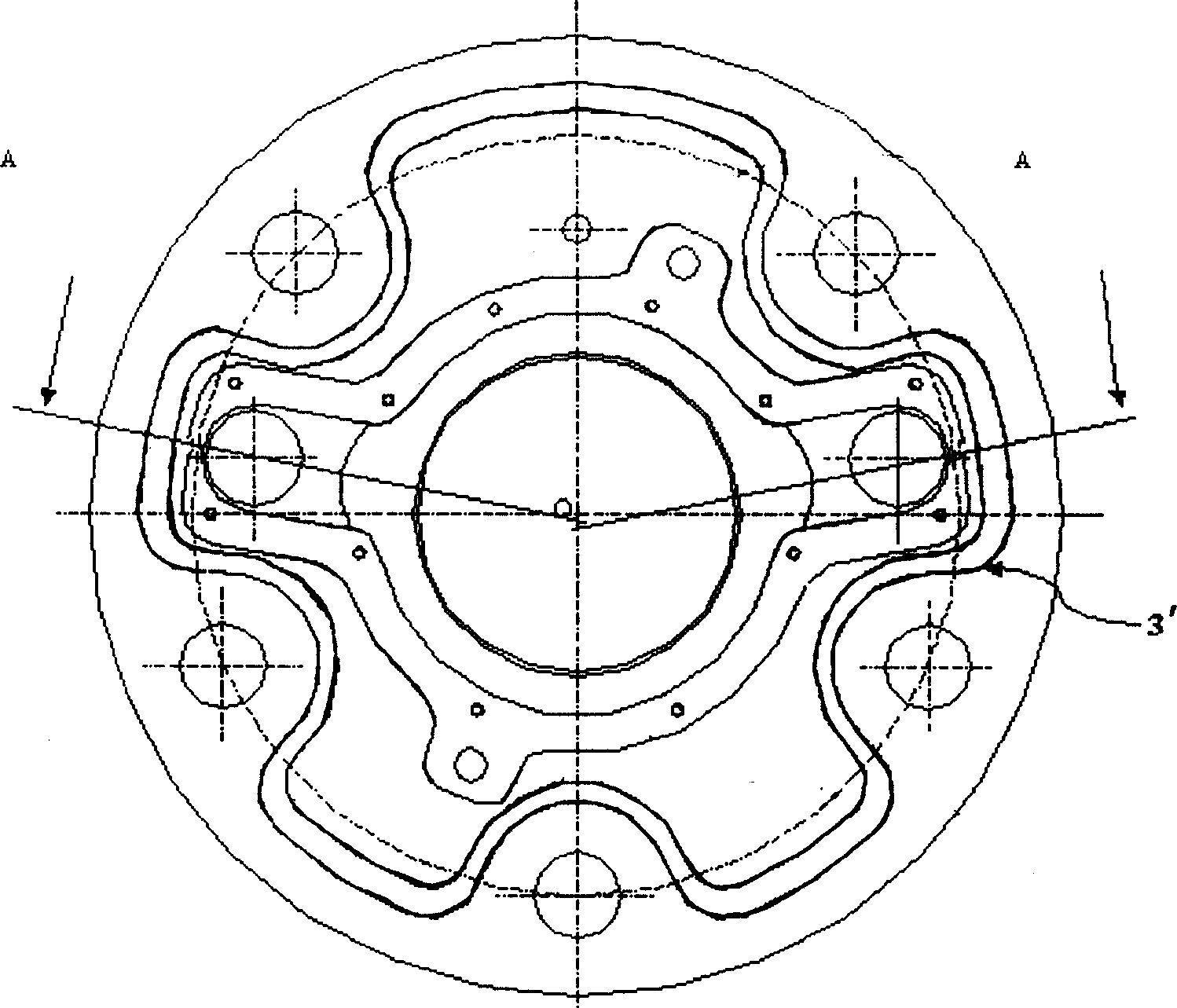
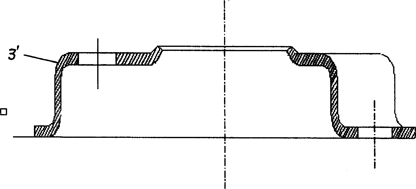
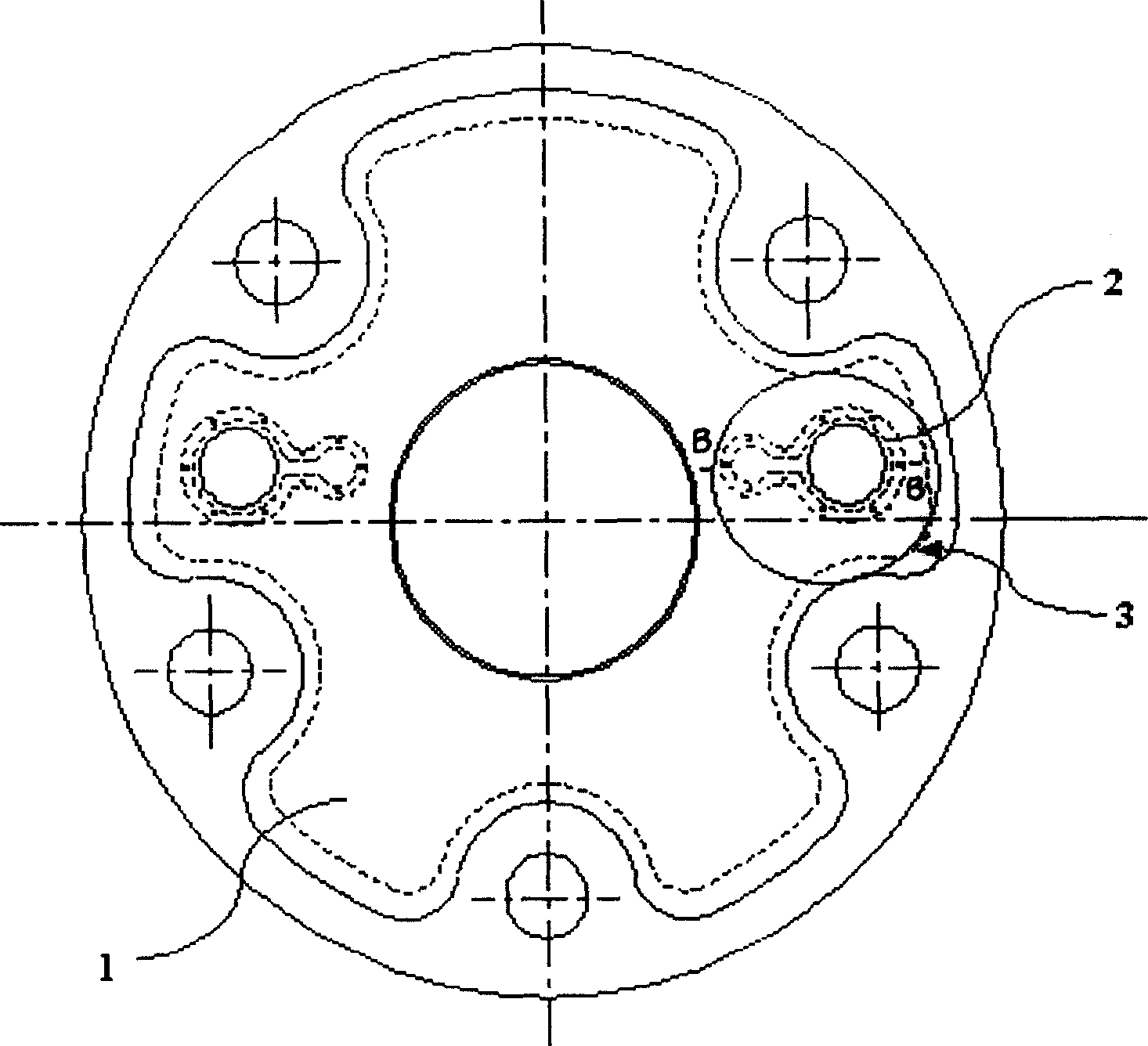
[0014] image 3 It is the bottom view of the compressor muffler of the present invention, Figure 4 yes image 3 The B-B section diagram. Such as image 3 , 4 As shown, the compressor muffler with resonant cavity of the present invention has a structure including a compressor muffler with a resonant cavity installed above the upper bearing with exhaust holes, and is respectively provided on both sides of the muffler central hole. The resonant cavities connected by connecting grooves, wherein one side of the resonant cavities close to the circumference are provided with exhaust holes.

[0015] The compressor muffler that the present invention has resonant chamber is realized like this:

[0016] Structurally, the present invention firstly changes the internal structure of the muffler of the compressor, and adds a resonant cavity. ...


PUM


Abstract

The invention discloses a compressor silencer with cavity, which comprises the following parts: silencer on the compressor top bearing, cavity on each side of silencer center through connecting slot, outlet hole on the cavity with one side near the circumference. The invention adapts Homhouze cavity to absorb special frequency band noise, which reduces noise by two decibel.

Description

technical field [0001] The invention relates to a compressor muffler, in particular to a compressor muffler with a resonant cavity. Background technique [0002] figure 1 is the bottom view of the existing compressor muffler, figure 2 yes figure 1 The A-A sectional view of the compressor shows that the upper and lower end faces of the cylinder block of the compressor are fixed with a sealed end face of the cylinder block, and the upper and lower bearings that support the rotation of the eccentric shaft. An exhaust valve (not shown in the figure) is installed on the upper end surface of the upper bearing. The exhaust valve discharges the refrigerant from the compression chamber of the cylinder block into the muffler, and then discharges the refrigerant from the muffler into the airtight casing. Above the airtight casing There is an exhaust pipe, and the exhaust pipe discharges the refrigerant in the closed casing into the refrigerant circulation system. [0003] After th...

Claims


Application Information

Patent Timeline
Patent Type & Authority Applications(China)
IPC IPC(8): F04C29/06
Inventor 杨小峰
Owner LG ELECTRONICS (TIANJIN) APPLIANCES CO LTD
Why Eureka
Try Eureka