
Method and device for machining composite parts formed from a carrier device and a stamping pad

A technology of processing equipment and supporting devices, applied in metal processing equipment, welding equipment, laser welding equipment, etc., can solve the problems of inability to individually adapt to special requirements, impossible to automate the production of multi-color and personalized design, etc.

Inactive Publication Date: 2010-08-04
特罗泰克产品及销售有限公司
View PDF4 Cites 0 Cited by
  • Summary
  • Abstract
  • Description
  • Claims
  • Application Information

AI Technical Summary

Problems solved by technology

Therefore, the disadvantage of the printing pads known in the prior art is that they cannot be individually adapted to the special requirements of the user in terms of the color design of the stamp, because so far only certain predetermined areas have been suitable for embossing different colors, These areas cannot, for example, be specified by the user for the color design of certain text symbols (Schriftzüge)
Automated production of multi-coloured and individually designed printing pads for use in self-inking stamps has hitherto also not been possible in the prior art

Method used


Image

  • Method and device for machining composite parts formed from a carrier device and a stamping pad
  • Method and device for machining composite parts formed from a carrier device and a stamping pad
  • Method and device for machining composite parts formed from a carrier device and a stamping pad

Examples


Embodiment Construction

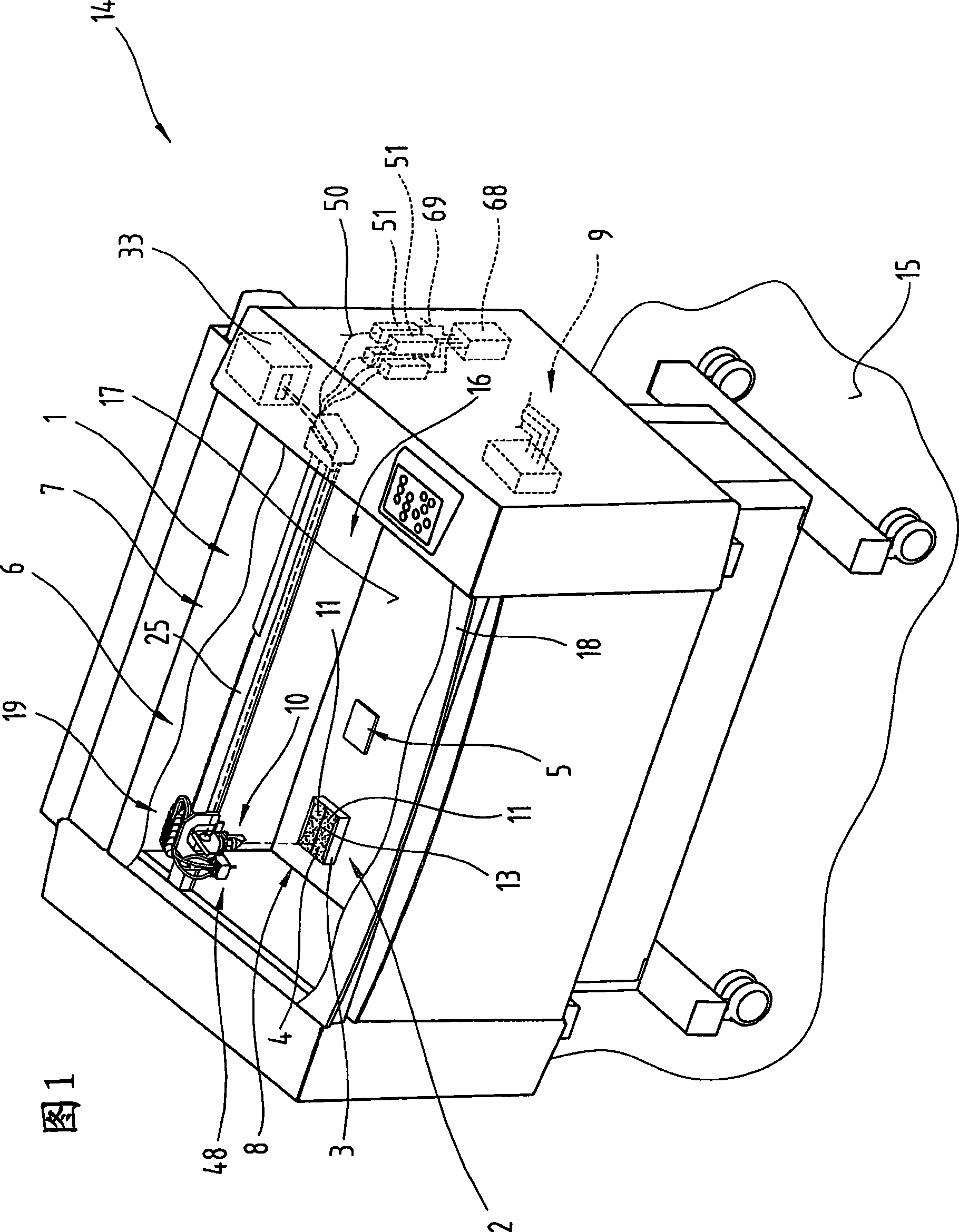
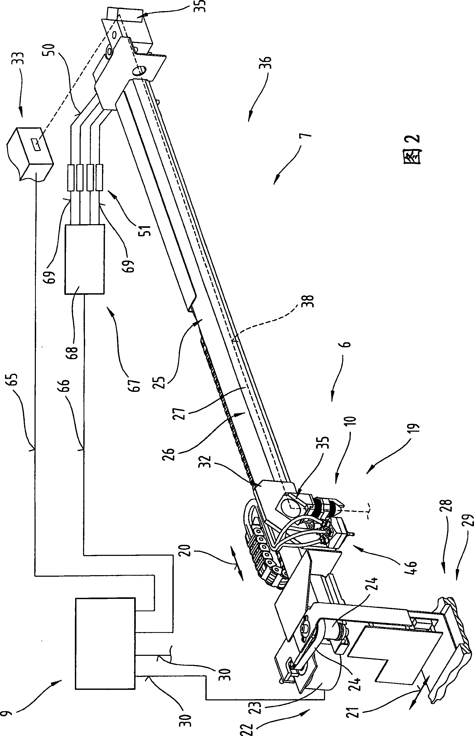
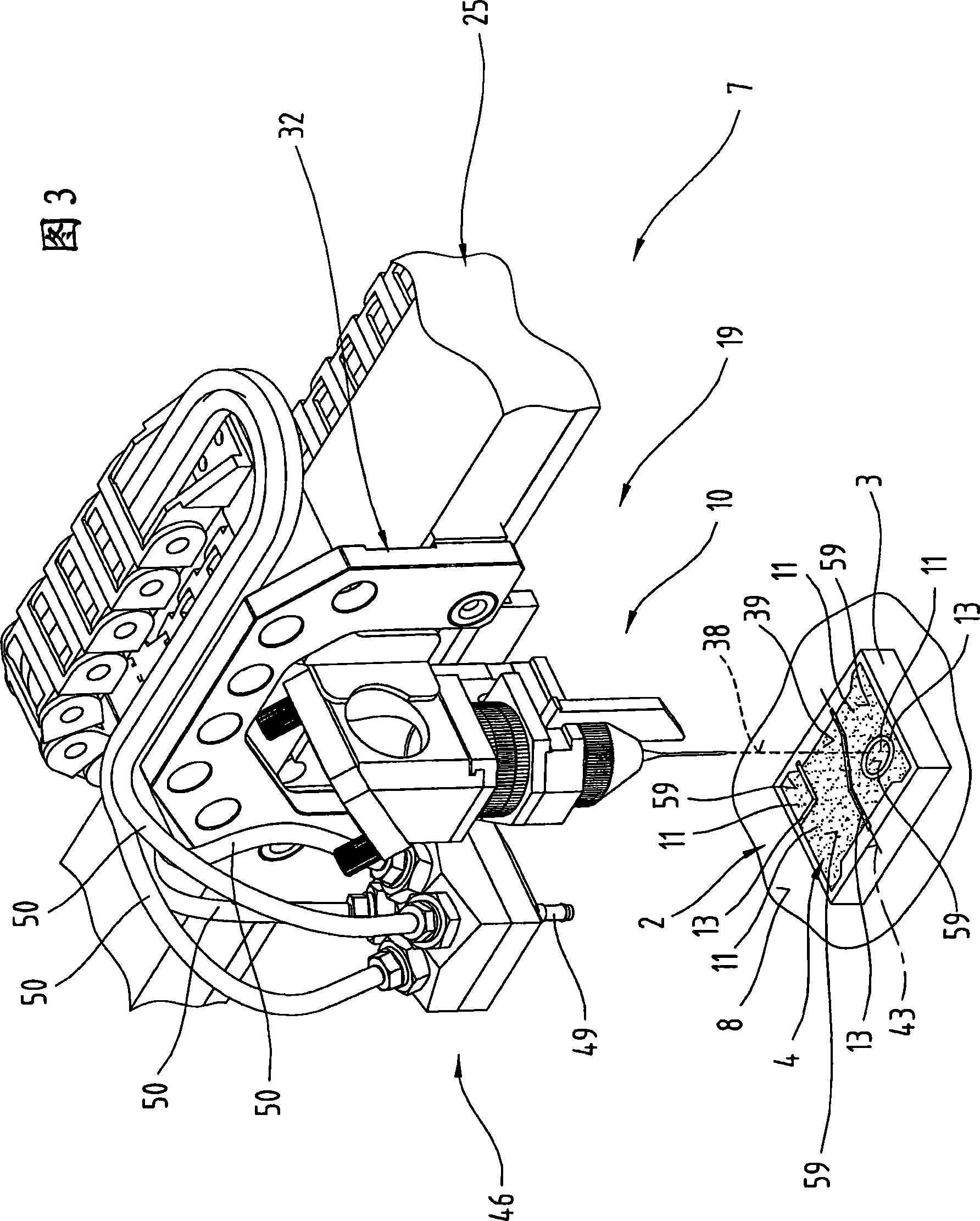
[0041] First of all, it is provided that in the different embodiments described, the same parts use the same symbols or the same component symbols, wherein the disclosed content contained in the entire description can be transferred to the same symbols with the same symbols or the same component symbols. part. Positional indications selected in the description, such as top, bottom, side, etc., refer to directly illustrated representations and can be sensibly transferred to the new position in the event of a position change. Furthermore, individual features or combinations of features of the different exemplary embodiments shown and described represent individual inventions or solutions according to the invention.

[0042] figure 1 In the middle is a processing device 1 according to the invention for processing at least one assembly 2, which is composed of at least one support device 3, in particular a printing pad holder, and a printing pad 4, where the processing device 1 ca...


PUM


Abstract

The invention relates to a method for machining composite parts (2), which are formed from at least one carrier device (3) and a stamping pad (4), with the aid of a machining device (1). In order to machine said composite part (2) at least one machining head (10) of a material machining device (6) and the composite part (2) re displaced in relation to each other, particularly on a plane XY, by means of a manipulating device (7) controlled by a control device (9). Material is removed from the composite part (2) by means of the material machining device (6). The material machining device (6) isused to divide the stamping pad (4) of the composite part (2), which is at least partially connected to the carrier device (3), into several stamping pad parts (11) which are distanced from each other by means of a separating joint (42). The invention also relates to a machining device (1) for carrying out said method.

Description

technical field [0001] The invention relates to a method for machining an assembly consisting of at least one support device and a stamping pad by means of a processing plant, wherein at least one processing head and the assembly of a material removal device are controlled by a controller for processing the assembly Controlled and / or adjusted manipulators move relative to one another, in particular in the XY plane, and material removal is carried out on the assembly by means of a material removal device; and a processing plant comprising at least one material removal device and a manipulator, wherein , the processing head of at least one material removal device is adjustable, in particular movable, at least in one XY plane by the manipulating device, and the manipulating device is connected and / or connectable to the controller for controlling and / or adjusting the manipulating device. Background technique [0002] From the prior art, multicolor, in particular two-color, print...

Claims


Application Information

Patent Timeline
Patent Type & Authority Patents(China)
IPC IPC(8): B23K26/40B41K1/54B23K26/36B41K1/46
CPCB23K26/405B41K1/46B23K26/4085B23K26/40B23K2103/16B23K2103/38B23K2103/50Y10T83/04
Inventor S·法曾
Owner 特罗泰克产品及销售有限公司
Learn More