Floor power supply device

A ground power supply and ground surface technology, applied in the direction of power supply circuit components, etc., can solve the problem of insufficient prevention of electric shock, and achieve the effect of preventing electric shock, small storage capacity, and durability.

Inactive Publication Date: 2006-05-03
SYST INNOVATION & RES
View PDF0 Cites 11 Cited by
  • Summary
  • Abstract
  • Description
  • Claims
  • Application Information

AI Technical Summary

Problems solved by technology

There are many systems that do not have a mechanism to block the holes in the pavement where the head protrudes
In addition, when power is not supplied, the contact body is not sufficiently submerged in the ground, and it is insufficient in preventing electric shock.
However, there is a threat...

Method used


Image

  • Floor power supply device
  • Floor power supply device
  • Floor power supply device

Examples


Embodiment Construction

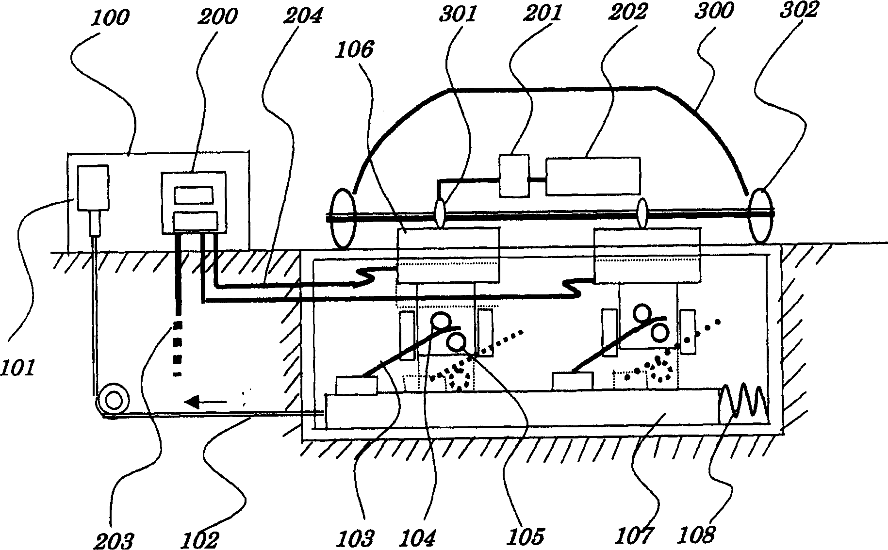
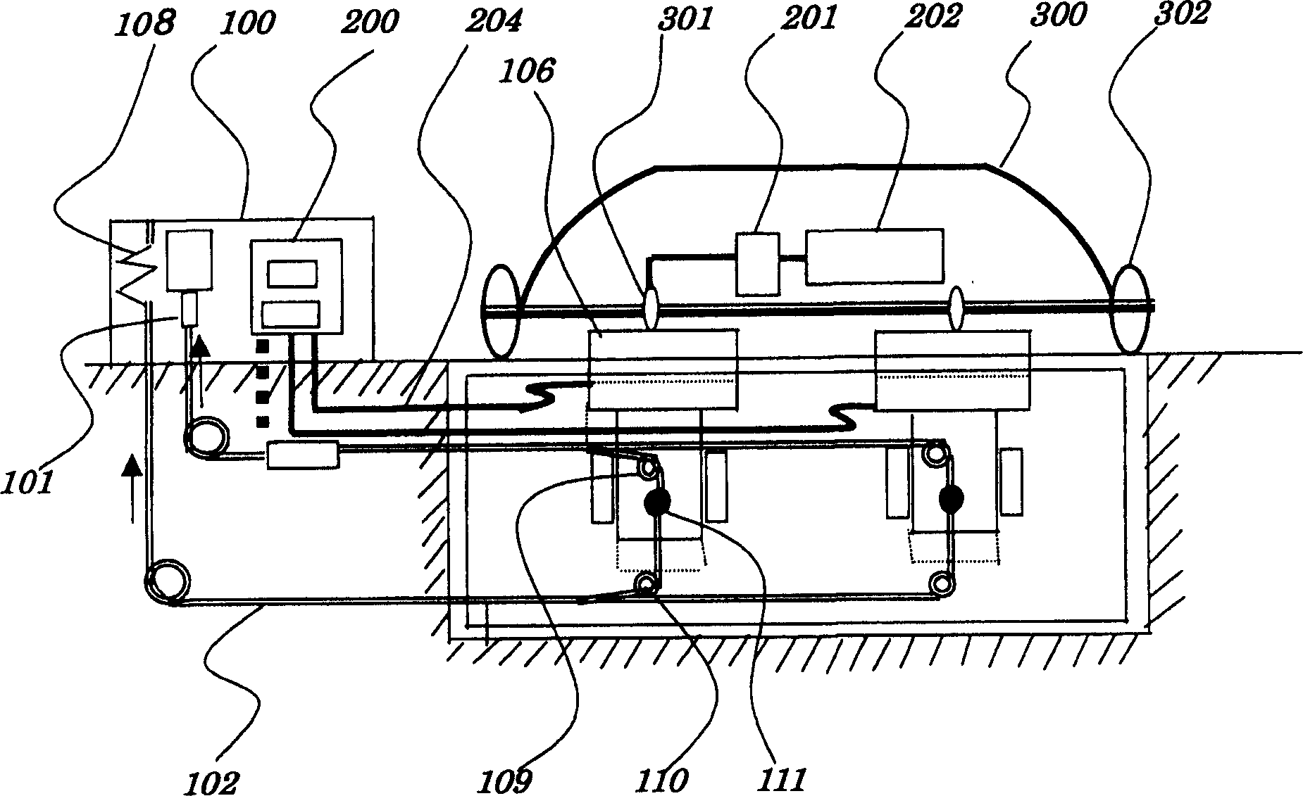
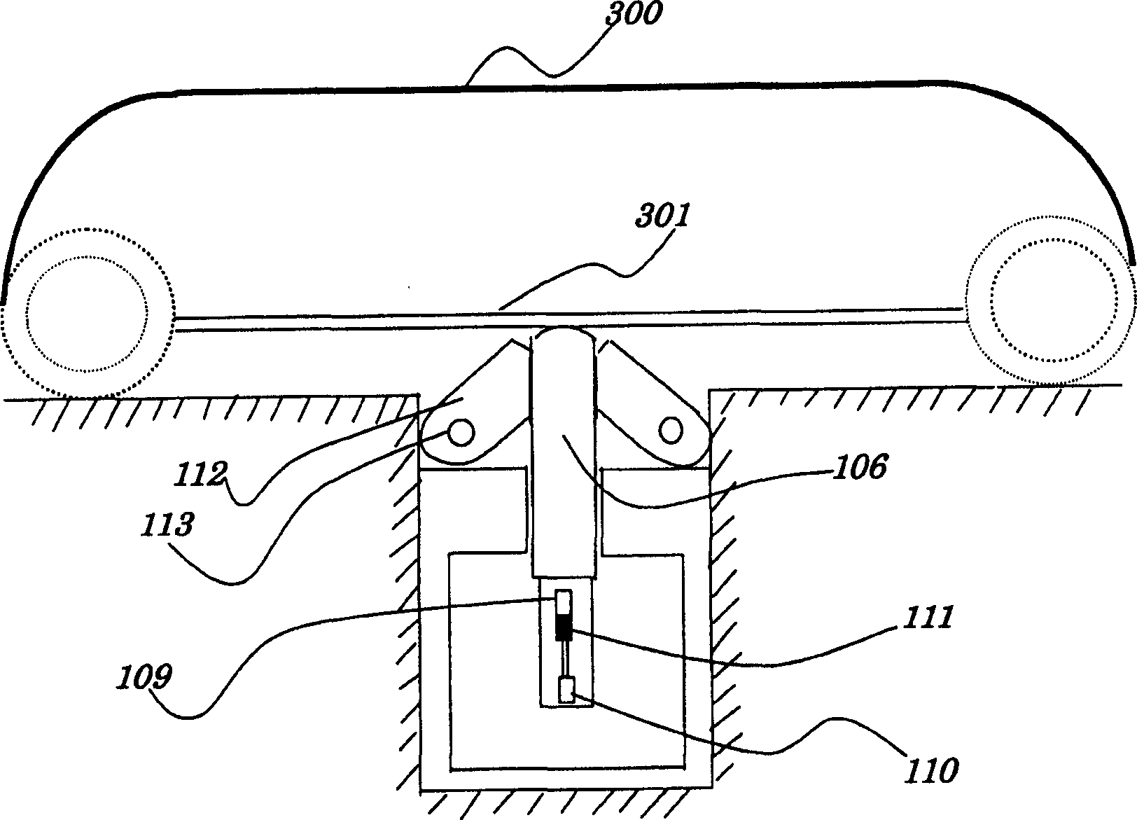
[0014] figure 1 It is a schematic cross-sectional view of the mechanical part that isolates electrical parts from the waterproof to the ground side. exist figure 1 Among them, 100 is a power supply box, 101 is a cylinder or a motor, 102 is a metal wire, 103 is an up and down driving spring, 104 is an upper push roller, 105 is a lower pressure roller, 106 is a contact body, 107 is a base rod, and 108 is a spring. 200 is an electrical circuit (power supply circuit, control circuit, etc.), 201 is a charging circuit, 202 is a capacitor (or battery), 203 is an input receiving line, 204 is a power supply line, 300 is a section of a tram, 301 is a receiving body, 302 is the wheel.

[0015] if refer to figure 1 Explain action, then at first cylinder 101 stretches metal wire 102 like arrow, base bar 107 just moves leftward, owing to drive spring 103 up and down, contact body 106 rises, stretches out head. Then, the electric car 300 approaches, and if the two groups of the receiving...


PUM


Abstract

Disclosed a ground power set is characterized in that: when the contactor projects from the ground, the door formed by the insulator which covers the contactor can form a inclined surface; and when the contactor sinks into ground, the door can be closed according to the seesaw theory, which can not be opened with wheel force or gambado, while avoiding the entrance of foreign matters. The invention can effectively avoid the electric shock and the entrance of foreign matters.

Description

technical field [0001] The present invention relates to opening a door made of an insulator, allowing electrodes embedded in the ground to protrude from the ground (road surface), and supplying electric power to electric devices such as trains covering the electrodes. Except when in use, the door is closed with an insulator, there is no unevenness, and there is little inflow of foreign matter, and maintenance based on regular water washing and air cleaner can be performed. Because there is no electric shock structure and control, it can be used in urban areas or scenic spots. Used in the power supply of streetcars, etc. Conventional tram systems are based on wire rods and wires, depending on the occasion, there is no track, and the on-board electric storage capacity is small, making it possible to realize a lightweight and inexpensive transportation system. In addition, it can supply power to patrol vehicles, equipment for disasters, electric excavators, electric cranes, and ...

Claims


Application Information

Patent Timeline
IPC IPC(8): B60M1/02
Inventor 藤冈一路
Owner SYST INNOVATION & RES
Why Eureka
Try Eureka