

Microwave oven control part mounting structure
An installation structure and microwave oven technology, applied in the field of microwave ovens, can solve the problems of increasing the development cycle and cost, and prone to errors, so as to avoid errors, reduce manufacturing costs, and reduce the development cycle.
- Summary
- Abstract
- Description
- Claims
- Application Information
AI Technical Summary
Problems solved by technology
Method used
Image

Examples
Embodiment Construction
[0026] In order to further understand the invention content, characteristics and effects of the present invention, the following examples are given, and detailed descriptions are as follows in conjunction with the accompanying drawings:
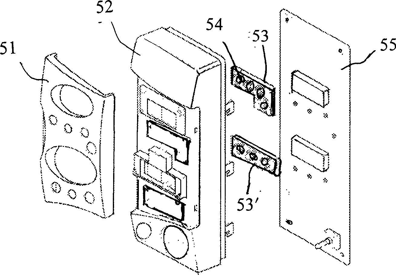
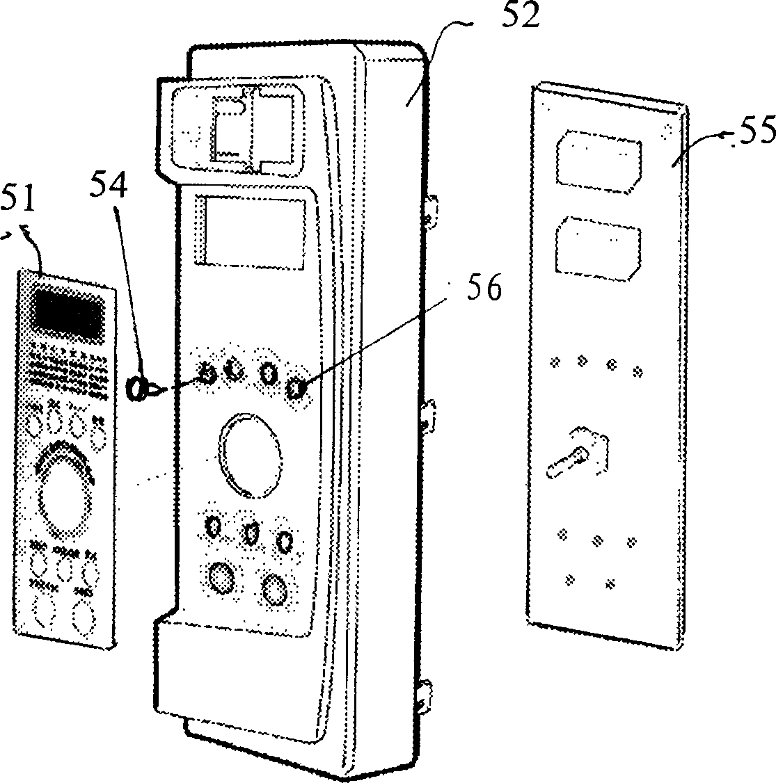
[0027] image 3 It is an exploded view of the structure of the control part of the microwave oven of the present invention.
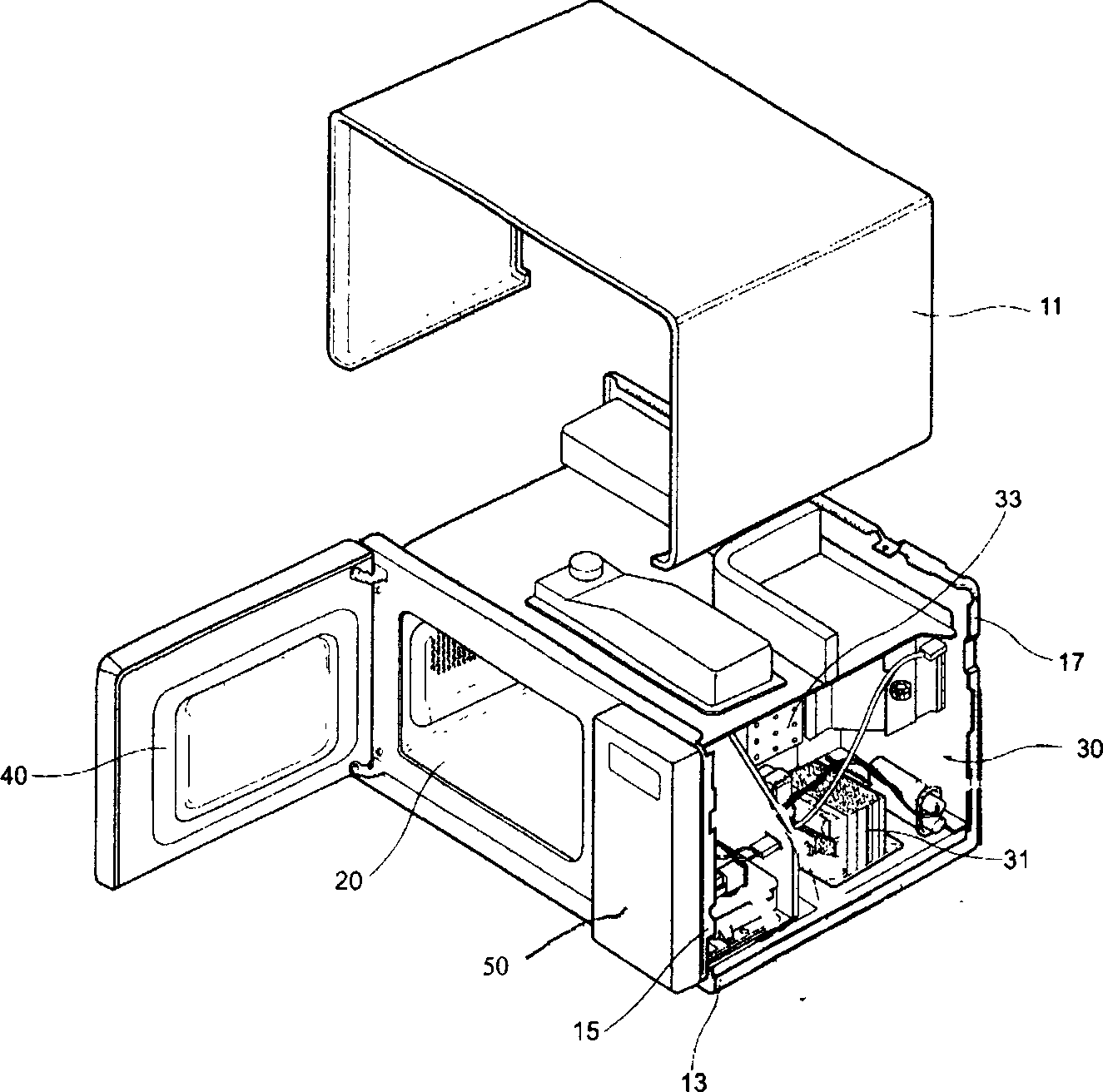
[0028] The microwave oven includes an outer casing forming an appearance, a cavity for placing food, and a storage room for controlling various electronic components for controlling the cavity. A door for selectively opening and closing the inner space of the oven cavity is provided at the front of the oven cavity, and the front end of the electric storage room is a control unit 50 .
[0029] Such as image 3 As shown, the control unit 50 includes a control panel 52 integrally injection-molded with the control button panel, a control front panel 51, a control button 54, and a control circuit board 55. The control pan...
PUM
 Abstract
Description
Claims
Application Information