
Optical deflection element and optical switch

A technology of optical deflector and optical converter, which is applied in the direction of optical components, optical waveguide, light guide, light guide, etc., and can solve the problem of low deflection angle accuracy

Inactive Publication Date: 2006-05-03
FUJITSU LTD
View PDF4 Cites 8 Cited by
  • Summary
  • Abstract
  • Description
  • Claims
  • Application Information

AI Technical Summary

Problems solved by technology

[0011] In the light converter using the above-mentioned conventional photonic crystal, it is possible to draw the optical path and obtain a large deflection angle, however, there is a problem that the accuracy of adjusting the deflection angle is not very high

Method used


Image

  • Optical deflection element and optical switch
  • Optical deflection element and optical switch
  • Optical deflection element and optical switch

Examples


no. 1 example

[0029] In this embodiment, a specific structure of a light deflection element employing the present invention will be described.

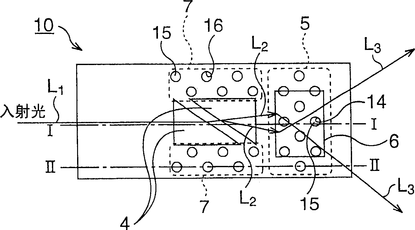
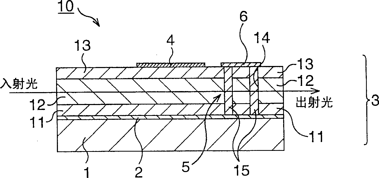
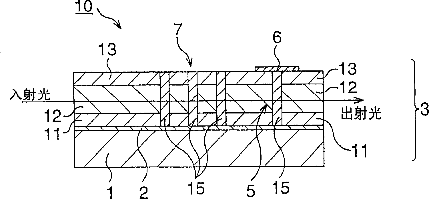
[0030] Figure 1A to Figure 1C shows the main components of the light deflecting element according to the first embodiment, wherein, Figure 1A is a top view diagram, Figure 1B is along Figure 1A The cross-sectional schematic diagram of the dotted line I-I, Figure 1C is along Figure 1A The schematic cross-section of the dotted line II-II in . In addition, FIGS. 2A to 2G and FIGS. 3A to 3E are schematic cross-sectional views showing the manufacturing method of the light deflection element according to the first embodiment in the order of steps (corresponding to the Figure 1A The cross-sectional schematic diagram of the dotted line I-I in).

[0031] Such as Figure 1A with Figure 1BAs shown, the light deflection element 10 of this embodiment is shaped to include: an optical waveguide 3 made of an electro-optic material on the element sub...


PUM


Abstract

A light deflection element is shaped to include: a prism electrode disposed on an optical waveguide; a first photonic crystal structure disposed in front of the prism electrode in a light propagation direction and at a position after light passes through the prism electrode; a control electrode via The optical waveguide on the first photonic crystal structure is arranged facing the opposite electrode layer; and the second photonic crystal structure is arranged on the side of the prism electrode parallel to the light propagation direction.

Description

[0001] Cross References to Related Applications [0002] This application is based upon and claims the benefit of priority from prior Japanese Patent Application No. 2004-311365 filed on October 26, 2004, the entire contents of which are hereby incorporated by reference. technical field [0003] The present invention relates to an optical deflection element for deflecting light and an optical converter for outputting an input optical signal to a desired channel. Background technique [0004] In recent years, photonic networks have increasingly required high-speed driving and high capacity than before, where optical signals have a wide frequency band and are multiplexed, so transmission equipment for photonic networks is also required to be multi-channel and high-speed driven. In addition, an optical cross-connect device used as a photonic network node is required to increase the number of channels and switch at a higher speed, so an optical converter such as Japanese Patent ...

Claims


Application Information

Patent Timeline
Patent Type & Authority Applications(China)
IPC IPC(8): G02B6/10G02F1/29
CPCB82Y20/00G02B6/1225G02B6/3546G02F1/313G02F2202/32G02F1/1309G02F2203/69
Inventor 青木刚近藤正雄栗原和明
Owner FUJITSU LTD
Learn More