Backlight source assembly

A technology of backlight source and components, applied in optics, nonlinear optics, instruments, etc., can solve the problems of increased external size, increased material cost of the fixing frame 12, inconvenient to replace the lamp board, etc., to increase the heat dissipation effect and stabilize the positioning. with limit effect

Inactive Publication Date: 2006-05-03
CORETRONIC
View PDF0 Cites 8 Cited by
  • Summary
  • Abstract
  • Description
  • Claims
  • Application Information

AI Technical Summary

Problems solved by technology

[0005] like Figure 1B As shown, however, generally the surrounding edge of the lamp panel 4 is a non-luminous area 4A, so the actual effective luminous area 4B of the lamp panel 4 will be smaller than the overall size of the lamp panel 4. In the known installation method, the lamp panel 4 needs to Placed on the lamp panel base 6 from above, so the side frame 602 extending outward around the lamp panel base 6 cannot cover the non-luminous area 4A around the edge of the lamp panel 4, so that the width (D) of the invalid display area will include The width of the light-emitting area 4A and the side frame 602, therefore, will cause the width (D) of the invalid display area on the edge of the flat panel display device 2 and the overall size of the backlight to increase, and it is necessary to use a fixed frame 12 with a larger frame to cover it. The invalid display area increases the material cost of the fixed frame 12
Moreover, if the assembled flat-panel display 2 is to be disassembled, it is necessary to dismantle the layers above the lamp board 4 one by one in order to take out the faulty lamp board 4, which is quite inconvenient to replace the lamp board 4.

Method used


Image

  • Backlight source assembly
  • Backlight source assembly
  • Backlight source assembly

Examples


Embodiment Construction

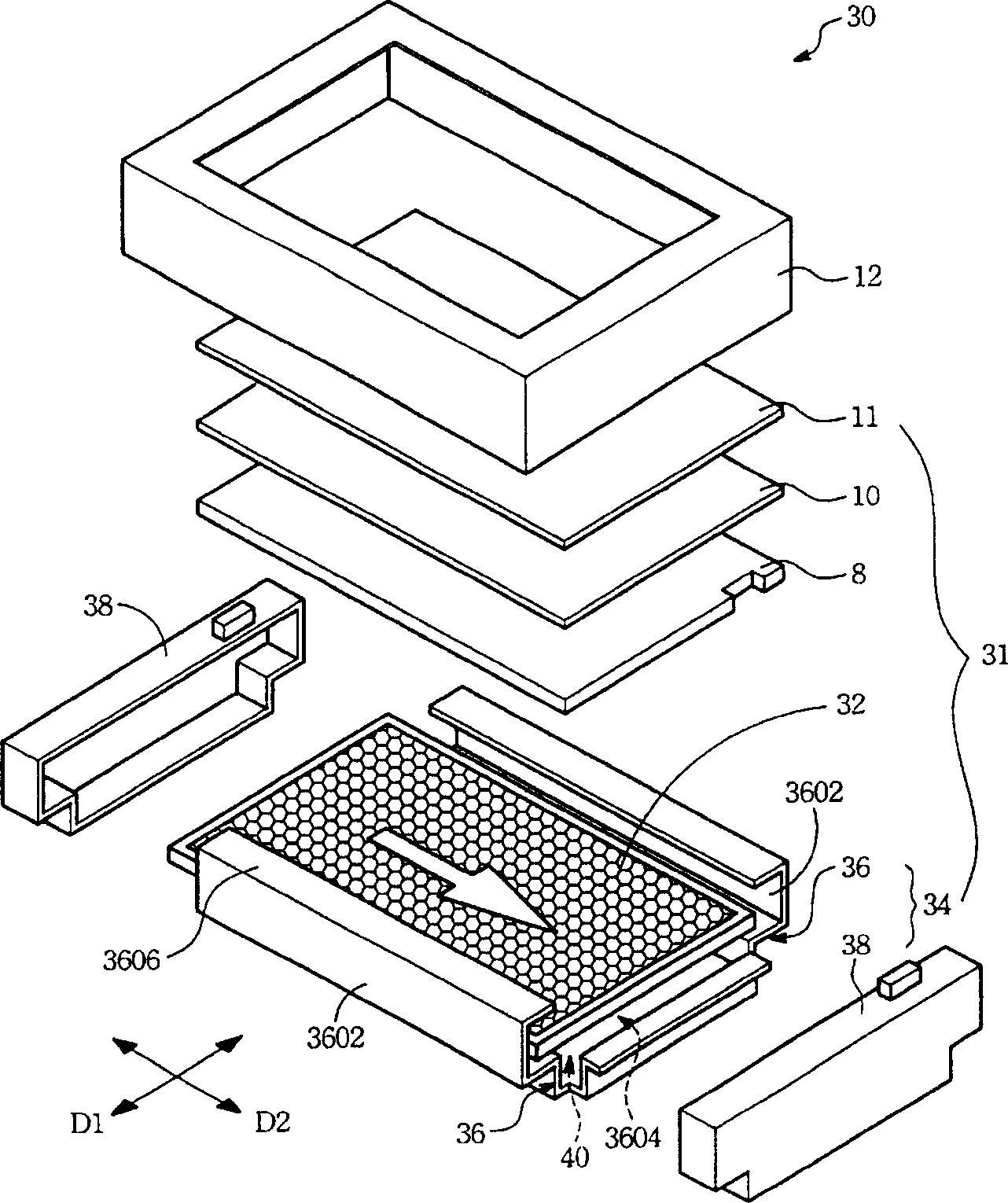
[0045] Refer to figure 2 . The present invention relates to a light board fixing device 34. The light board fixing device is used in a backlight assembly 31 to fix a light board 32. The light board fixing device 34 includes a light board base 36 and at least one limiter. Bit border 38.

[0046] The light board base 36 is arranged on the bottom surface of the light board 32. At least two opposite sides of the light board base 36 extend upward to form a side frame 3602, which is used to limit the light to the first direction D1 of the two-dimensional space of the light board 32. Plate 32, side frame 3602 and then horizontally extend the covering edge 3606 inward for the diffusion plate 8 and the optical material 10 to carry. The width of the covering edge 3606 can be set according to the width of the non-light emitting area 32A of the light board 32 to effectively shield No light-emitting area 32A.

[0047] The limiting frame 38 is sleeved on the side of the open end 3604 of the li...


PUM


Abstract

The invention relates to a negative phototropic component which comprises a lamp plate, a lamp plate base and a dismantling / combine spacing frame. The lamp plate base is positioned on one side of the lamp plate bottom side; the lamp plate base has two sides frame to hold the responding two sides of the lamp plate. The spacing frame is cover-connected with the flack of the lamp base open end, which is used to space the lamp plate inside the lamp base.

Description

Technical field [0001] The invention relates to a backlight source assembly, in particular to a light board fixing device for fixing a light board in a backlight source assembly using a light board as a light source. Background technique [0002] Flat-panel display devices have gradually become the main display devices. Since the liquid crystal display panels of the flat-panel display devices are non-self-luminous elements, a backlight assembly is particularly required as a light-emitting element. Among the light sources used in flat display devices, the direct type backlight assembly is a widely used light source. [0003] In the direct-lit backlight assembly, multiple light tubes can be arranged in parallel as the light source. In addition, the light board can also be used as the light source. Compared with the light tube, the light board also has the advantages of easy assembly and uniform illumination. . [0004] Refer to Figure 1A , Figure 1A It is a schematic diagram of a...

Claims


Application Information

Patent Timeline
Patent Type & Authority Applications(China)
IPC IPC(8): G02F1/1335G02F1/133
Inventor 黄炳锋潘柏志
Owner CORETRONIC
Why Eureka
Try Eureka