

Sensing steering axis inclination and camber with an accelerometer
An accelerometer and acceleration technology, applied in the field of wheel alignment systems, can solve the problems of large sensors, damage accuracy, and high cost
- Summary
- Abstract
- Description
- Claims
- Application Information
AI Technical Summary
Problems solved by technology
Method used
Image

Examples
Embodiment Construction
[0024] The disclosure is now described more fully with reference to the accompanying drawings in which several embodiments are shown. Those skilled in the art will recognize that methods, apparatus, systems, data structures, and computer readable media implement a feature, function, or mode of use described herein. For example, an apparatus embodiment may perform corresponding steps or actions of a method embodiment.
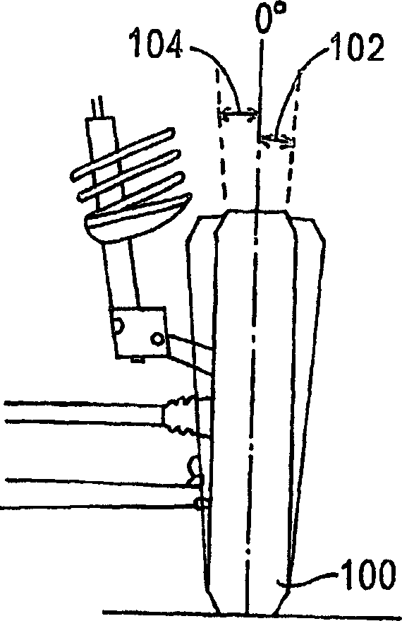
[0025] figure 1 Camber angles measured by an exemplary wheel alignment system are shown. Camber is the angle of the wheel 100 when viewed from the front of the vehicle, usually measured in degrees. If the top of the wheel 100 slopes outward from the center of the vehicle, the camber is positive, as indicated by angle 102 . If the top of the wheel 100 slopes inward toward the center of the vehicle, the camber is negative, as indicated by angle 104 .
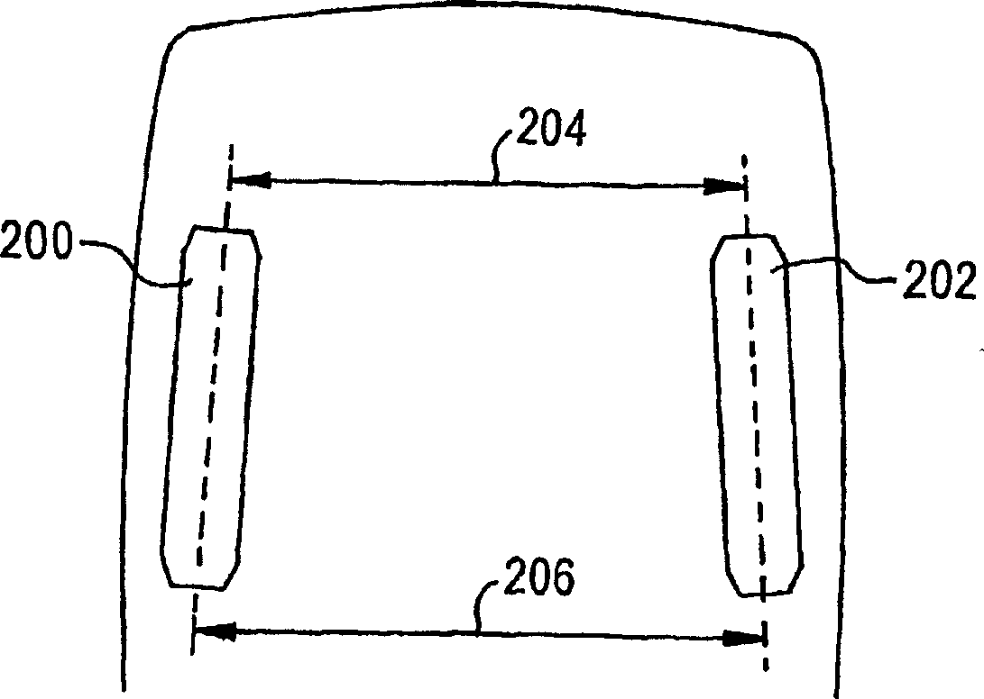
[0026] figure 2 The bead measured by an exemplary wheel alignment system is shown. The bead of two adjacen...
PUM
 Abstract
Description
Claims
Application Information