Process for producing glass optical element and method for determining glass component of glass blank
What is AI technical title?
AI technical title is built by PatSnap AI team. It summarizes the technical point description of the patent document.
A technology for optical components and manufacturing methods, which are used in optical components, glass molding, glass pressing, etc.
Inactive Publication Date: 2003-09-10
HOYA CORP
View PDF2 Cites 5 Cited by
Summary
Abstract
Description
Claims
Application Information
AI Technical Summary
This helps you quickly interpret patents by identifying the three key elements:
Problems solved by technology
Method used
Benefits of technology
Problems solved by technology
[0018] The method described in JP-A-7-330354 intends to eliminate the deviation between the predicted value of the index drop of the molded lens and the actual value, but does not provide any solution for the drop itself
Method used
Image
Click on the blue label to locate the original text in one second.
Reading with bidirectional positioning of images and text.
Examples
Embodiment
[0148] Next, the present invention will be described in more detail while finding the best embodiment.
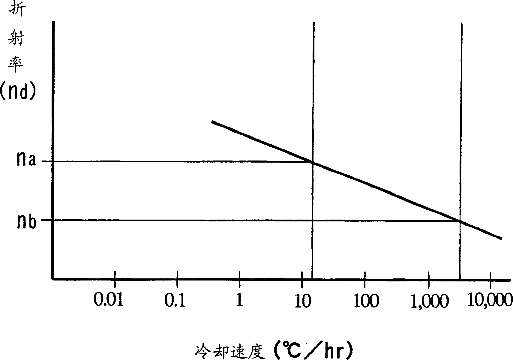
[0149] In the following examples, the refractive index n is used d , Abbe number γ d as an optical constant.
reference example 1
[0151] Using barium borate optical glass (basic composition: SiO 2 37.8wt%, B 2 o 3 24.0wt%, Al 2 o 3 5.3wt%, Li 2 O8.5wt%, CaO5.0wt%, BaO16.1wt%, La 2 o 3 3.3wt%, As 2 o 3 0.5wt%, Sb 2 o 3 0.2 wt%, Tg: 500 degrees), to produce glass lenses.
[0152] The above-mentioned barium borate glass was melted, flowed down from an outflow pipe, cut and cooled (quenched in the atmosphere) to obtain a preform (glass blank for press molding) in the shape of an oblate sphere. The strain of this preform was large, and the refractive index could not be measured, but it was estimated to be a rather low value. Keep at Tg+30 degrees for 2 hours, cool to the strain point below -50 degrees at a cooling rate of 30 degrees / hour, and measure the refractive index (n) at room temperature d 1.58900, gamma d 61.30). These are referred to as the standard refractive index and the standard Abbe number.
[0153] The above-mentioned quenched preform is sent to a press-forming process to be pres...
Embodiment 1
[0157] Implement the refractive index n of the preform shown in reference example 1 under Tg+30 degrees for 2 hours, and cooling (processing under specified conditions) at a cooling rate of 30 degrees / hour d 1.58900 and the Abbe number¶ d 61.30 is the standard refractive index and standard Abbe number, which is determined by n 1 And γ1 said the refractive index and Abbe.
[0158] In addition, in Reference Example 1, by press-forming the glass of the above-mentioned composition under the above-mentioned conditions, it becomes n d 1.58600, Abbe number γ d 61.25. That is, n 2 for n d 1.58600, γ2 for γ d 61.25.
[0159] That is, n 1 -n 2 300×10 -5 , γ1-γ2 is 0.05.
[0160] And, as the expected value of the lens design (n 3 and γ3), select and n 1 and the same n as γ1 d 1.58900 and gamma d 61.30, try lens shaping.
[0161] Alternatively, the modulation standard refractive index ratio n 3 High 300×10 -5 The glass blank is used as a preform (glass blank), so that af...
PUM
Property
Measurement
Unit
refractive index
aaaaa
aaaaa
refractive index
aaaaa
aaaaa
Abbe number
aaaaa
aaaaa
Abstract
Provided is a method for manufacturing glass optical elements having desired refractive index with a simple and convenient rule and a high precision even when glass blank material supplied for a press molding working procedure suffers a thermal hysteresis after being melted. Said method for manufacturing glass optical elements of desired refractive index n3 by means of a press molding process (namely the first manufacturing method mentioned below) comprises utilizing a shaping mould to press molding a softened glass material in a pressing mold and then cooling it. The method comprises preparing a interim optical element by means of the press molding process from a glass material of a prescriptive composition, measuring a refractive index n2 of the interim optical element, obtaining the difference between a standard refractive index n1 of the prescriptive composition processed with a prescriptive condition and the refractive index n2 of the interim optical element mentioned above, preparing a certain glass composition having standard refractive index substantially of the value which is obtained by adding the difference to the refractive index n3, and preparing an optical element by means of the press molding process from a glass material of the certain glass composition.
Description
technical field [0001] The present invention relates to a method for manufacturing a high-precision glass optical element. Specifically, the present invention relates to a method of forming a softened glass blank by pressing a molding mold with a specified surface accuracy, and transferring the molding surface of the molding mold to the above-mentioned glass blank. Above, a method of manufacturing a glass optical element with desired surface accuracy and optical characteristics. Background technique [0002] In recent years, precision press forming technology has been developed that does not require grinding and grinding steps after press forming, and a large number of lenses, especially aspheric lenses, have been produced by this technology. [0003] In the manufacture of glass optical components, the management of optical properties is indispensable. This is determined by the specification of the optical product to which the glass optical element is applied, and is usuall...
Claims
Application Information
Patent Timeline
Application Date:The date an application was filed.
Publication Date:The date a patent or application was officially published.
First Publication Date:The earliest publication date of a patent with the same application number.
Issue Date:Publication date of the patent grant document.
PCT Entry Date:The Entry date of PCT National Phase.
Estimated Expiry Date:The statutory expiry date of a patent right according to the Patent Law, and it is the longest term of protection that the patent right can achieve without the termination of the patent right due to other reasons(Term extension factor has been taken into account ).
Invalid Date:Actual expiry date is based on effective date or publication date of legal transaction data of invalid patent.

