Soft tooling forming method used for reinforcing rib and web plate co-bonding and application

A forming method and technology of reinforcing ribs, which are applied in the soft tooling forming and application fields for co-bonding of reinforcing ribs and webs, can solve the problems of long manufacturing cycle, affecting the internal forming quality of parts, and lagging heating rate, etc. Achieve the effect of improving pass rate and efficiency, avoiding thermal hysteresis effect, and avoiding thickness tolerance

Inactive Publication Date: 2020-02-21
航天海鹰(镇江)特种材料有限公司
View PDF7 Cites 5 Cited by
  • Summary
  • Abstract
  • Description
  • Claims
  • Application Information

AI Technical Summary

Problems solved by technology

The disadvantages of using the mandrel mainly include the following three aspects: (1) Since the mandrel itself has a certain rigidity, it is difficult to achieve uniform and accurate conduction of external pressure through the mandrel, and it is easy to cause the thickness of the reinforcing rib of the part to be out of tolerance; (2) ) Since the mandrel has a certain thickness

Method used


Image

  • Soft tooling forming method used for reinforcing rib and web plate co-bonding and application
  • Soft tooling forming method used for reinforcing rib and web plate co-bonding and application
  • Soft tooling forming method used for reinforcing rib and web plate co-bonding and application

Examples


Embodiment 1

[0032] This embodiment is to make soft tooling for co-gluing of stiffeners and webs, including the following steps:

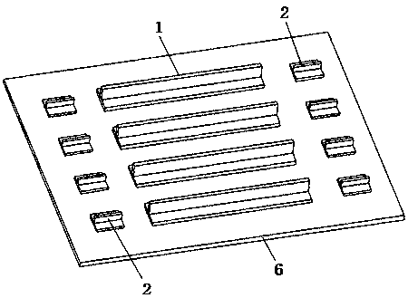
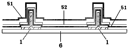
[0033] 1) Making fake parts: Since the web part of the composite material part is in a solidified state, the soft tooling is only used for the molding of the rib part of the composite material part, and ensures that after the part is formed, the rib part and the web part The relative position degree meets the design requirements. The method adopted in this embodiment is to manufacture a metal dummy 1 with a reinforcing rib that is completely consistent with the external dimensions of the reinforcing rib of the composite material part through mechanical processing. The cross section of the reinforcing rib is T-shaped or I-shaped. At the same time, the positioning device part 2 is made, and the positioning device part 2 has a positioning assembly relationship with the bottom plate 3 of the composite material part forming mold, that is, the corresponding position ...

Embodiment 2

[0039] In this example, the soft tooling made in Example 1 is used for the co-bonding of the ribs and the web, and the steps are as follows:

[0040] S1: Assembling the web: Assembling and fixing the web 8 of the composite material part in a solidified state on the mold bottom plate 3 of the composite material part. Since the web 8 is in a solidified state, positioning holes 81 can be drilled on it, and at the same time, positioning pins 32 are set on the mold base plate 3 of the composite material part, and through the cooperation of the hole pins, it is ensured that the web plate 8 is positioned on the base plate of the mold base plate of the composite material part. The position on 3 is fixed.

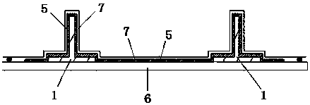
[0041] S2: Fill the rib prepreg: fill the pre-compacted rib prepreg 9 in the cavity formed by the stiffener metal dummy 1 on the soft tooling 5 made in embodiment 1, as Figure 4 shown.

[0042] S3: Assembling the soft tooling: the soft tooling 5 filled with rib prepreg in step S2...


PUM


Abstract

The invention discloses a soft tooling forming method used for reinforcing rib and web plate co-bonding and application. Rubber and reinforced fiber prepreg are paved on a reinforcing rib metal fake part and a positioning device part to make soft tooling, and the soft tooling is used for reinforcing rib and web plate co-bonding. Compared with a traditional core mold forming method, the soft tooling can evenly and precisely transmit pressure applied by a hot pressure tank, the phenomenon of thickness overproof appearing in a composite part is avoided, meanwhile, the soft tooling is thin, and the thermal hysteresis effect of the reinforcing rib portion can be avoided. The forming quality of the composite product can be effectively ensured, the production yield and efficiency can be improved,meanwhile, the positioning device ensures the reinforcing rib and web plate relative position precision of the composite product obtained through reinforcing rib and web plate co-bonding, and the product quality is ensured.

Description

technical field [0001] The invention relates to a forming method and application of a soft tooling used for the co-gluing of reinforcing ribs and webs. Background technique [0002] Resin-based carbon fiber composite materials have superior properties such as specific strength and specific stiffness, strong designability, good fatigue fracture resistance, corrosion resistance, and good dimensional stability. They are currently widely used in aviation, aerospace, transportation and other fields. High-performance structural materials. Among various carbon fiber composite molding processes, the autoclave process has uniform molding temperature and pressure, and has good adaptability to parts of different materials, shapes, sizes and structures. One of the main process methods of material components. [0003] With the increasing requirements for the strength and stiffness of composite parts, the structure of the parts is becoming more and more complex. Among them, the web stru...

Claims


Application Information

Patent Timeline
IPC IPC(8): B29C70/34B29C70/54B29C70/78
CPCB29C70/342B29C70/542B29C70/78
Inventor 谢海洋郭渊马秀菊盛毅黎玉钦孙龙岗
Owner 航天海鹰(镇江)特种材料有限公司
Why Eureka
Try Eureka