Method for achieving large-size I-beam reinforced skin structure composite workpiece co-cementing forming through soft tool

A technology of composite materials and I-beams, which is applied to household components, other household appliances, household appliances, etc., can solve problems such as inconvenient operation, high precision requirements for mold processing, skin part thickness and non-destructive testing tolerance, etc., to achieve Improve pass rate and efficiency, avoid thermal hysteresis effect, and avoid the effect of out-of-tolerance profile

Inactive Publication Date: 2019-05-24
航天海鹰(镇江)特种材料有限公司
View PDF4 Cites 0 Cited by
  • Summary
  • Abstract
  • Description
  • Claims
  • Application Information

AI Technical Summary

Problems solved by technology

[0007] Although the structural strength of the I-shaped reinforced beam has been improved after curing, under the high temperature and high pressure environment, due to the large bearing moment of the vertical rib of the I-shaped beam, there are still distortions, positional deviations, skin and the bottom surface of the long truss. There are risks such as dents in the contact area, so the role of the metal mandrel is to maintain the shape and position of the I-shaped reinforcing beam to ensure the quality of product molding
[0008] The shortcomings of using the metal mandrel method to form I-beams mainly include the following five aspects: (1) Since the mandrel itself has a certain rigidity, and the metal mandrel and the mold bottom plate must be accurately positioned through the hole pins, the outside world is transmitted through the mandrel. The pressure is difficult to be uniform and accurate, and it is easy to cause the thickness of the skin part of the part and the non-destructive testing to be out of tolerance; (2) Since the core mold has a certain thickness and the thickness is not uniform, according to the heat transfer effect, the skin part of the part is different The heating rate of the area will be different, which will affect the internal molding quality of the part, resulting in a large amount of deformation after the part is cooled and demolded; It has a certain structural rigidity, and at the same time, the composite material parts will inevitably have slight deformation after forming. Therefore, it is difficult to achieve a tight fit between the I-shaped beam and the metal mandrel. If the assembly is forced, it will inevitably cause stress inside the I-shaped reinforced beam. , which will lead to contour and non-destructive defects after the product is cured; (4) Since the mandrel is made of metal, it has a large weight and is very inconvenient to operate, and it is easy to deform when the length direction is large, which affects the overall size of the product; ( 5) Based on the co-cementation process of the metal mandrel, the mold design is relatively complicated, and the precision of the mold processing is high, which greatly increases the cost and cycle of mold manufacturing, repair and later maintenance

Method used


Image

  • Method for achieving large-size I-beam reinforced skin structure composite workpiece co-cementing forming through soft tool
  • Method for achieving large-size I-beam reinforced skin structure composite workpiece co-cementing forming through soft tool
  • Method for achieving large-size I-beam reinforced skin structure composite workpiece co-cementing forming through soft tool

Examples


Embodiment Construction

[0025] Further description will be made below in conjunction with specific embodiments and accompanying drawings.

[0026] The detailed flow of the soft tooling to realize the co-bonding of I-beam reinforced skin structure composite parts is as follows:

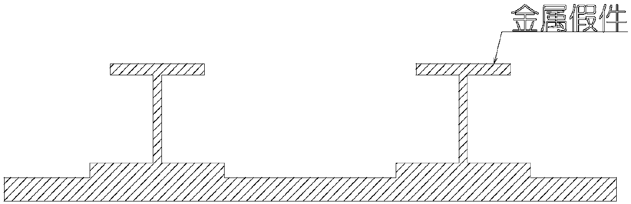
[0027] 1. Through the method of mechanical manufacturing, process a metal dummy that is exactly the same in size as the reinforced skin of the I-beam (such as figure 1 ), as a molding die for soft tooling;

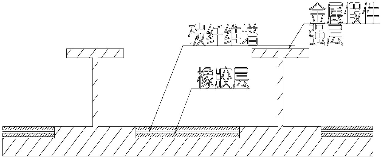
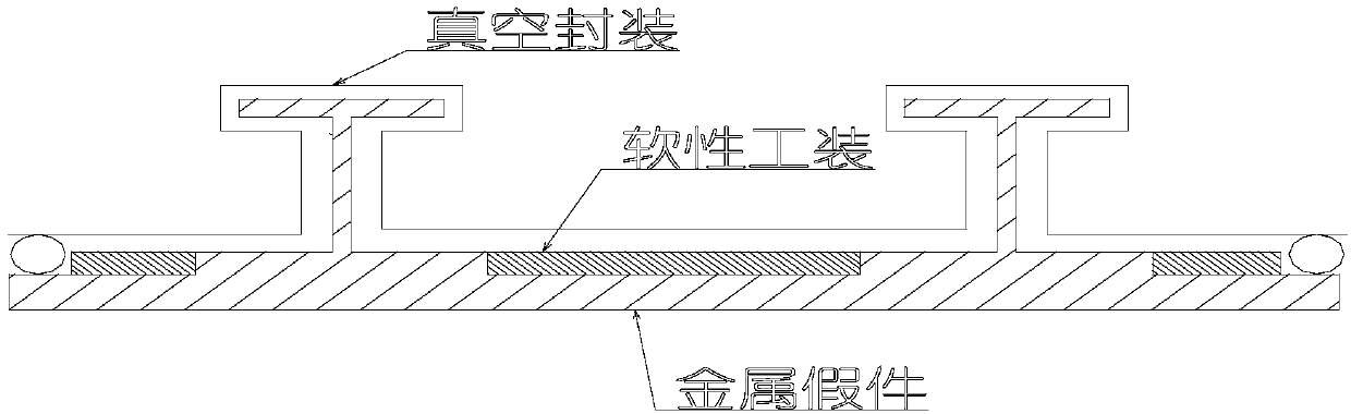
[0028] 2. Lay soft tooling in the cavity formed between the I-beams on the metal dummy (such as figure 2 ). The soft tooling uses rubber as the main material, and the rubber is laid layer by layer in the cavity, and carbon fiber prepreg is laid in the middle of the rubber layer as a reinforcement layer to improve the overall rigidity of the soft tooling. The number of layers of material mainly depends on the size and structural complexity of composite parts. Finally seal the vacuum bag (such as image 3 ), and accor...


PUM


Abstract

The invention discloses a method for achieving large-size I-beam reinforced skin structure composite workpiece co-cementing forming through a soft tool. The fiber-reinforced rubber soft tool is formedthrough a metal mold, the soft tool serves as part of a co-cementing mold after being formed, and the co-cementing process of an I-beam reinforced skin is completed. Compared with a traditional mandrel forming method, the soft tool provided by the invention can uniformly and precisely transmit pressure applied by an autoclave, the phenomenon that the thickness of a composite workpiece is out of tolerance is avoided, meanwhile, product profile keeping is facilitated through balanced pressure, product distortion is prevented, and the thermal hysteresis effect can be avoided through the soft tool; and in this way, the forming quality of the workpiece can be effectively ensured, and the production yield and efficiency are improved.

Description

technical field [0001] The invention belongs to the technical field of advanced composite material manufacturing, especially relates to the manufacture of high-performance carbon fiber composite material structural parts in the aircraft, spacecraft and automobile industries, and particularly relates to a kind of soft tooling to realize the composite material manufacturing of large-size I-beam reinforced skin structure. A method of co-cementing molding. Background technique [0002] Resin-based carbon fiber composite materials have superior properties such as specific strength and specific stiffness, strong designability, good fatigue fracture resistance, corrosion resistance, and good dimensional stability. They are currently widely used in aviation, aerospace, transportation and other fields. High-performance structural materials. Among various carbon fiber composite molding processes, the autoclave process has uniform molding temperature and pressure, and has good adaptab...

Claims


Application Information

Patent Timeline
Patent Type & Authority Applications(China)
IPC IPC(8): B29C70/44B29C70/54B29L31/30
Inventor 马秀菊贾傲郭源林丽萍童心
Owner 航天海鹰(镇江)特种材料有限公司
Why Eureka
Try Eureka