Manufacturing method for soft mode for I-beam composite material piece forming and application thereof

A technology of composite materials and manufacturing methods, which is applied to the production of soft molds for forming I-beam composite parts and its application fields, which can solve the problems of low manufacturing success rate, irreparable repair, and long manufacturing cycle, and achieve guaranteed surface and dimensional accuracy, easy post-maintenance, and improved pass rate and efficiency

Inactive Publication Date: 2020-02-21
航天海鹰(镇江)特种材料有限公司
View PDF5 Cites 9 Cited by
  • Summary
  • Abstract
  • Description
  • Claims
  • Application Information

AI Technical Summary

Problems solved by technology

The disadvantages of using these two processes to form I-beams mainly include the following aspects: 1) Since the mandrel itself has a certain rigidity, it is difficult to achieve uniform and accurate transmission of external pressure through the mandrel, which is likely to cause variable cross-section thin-wall composite The thickness of the material part is out of tolerance, and it is difficult to meet the thickness tolerance requirements
2) Since the core mold has a certain thickness and the thickness is not uniform, according to the heat transfer effect, the heating rate of different regions of the part will be different, which will affect the internal molding quality of the part, resulting in a large part after cooling and demoulding. Deformation; at the same time, large parts with drastic changes in thickness and many layer loss areas have high requirements for metal mold combinations, and general mold forming methods are difficult to meet the non-destructive requirements of civil aircraft
3) Since the core mold is made of metal, it has a large weight and is very inconvenient to operate
At the same time, the manufacturing and maintenance costs of the metal mandrel are relatively high, and the manufacturing cycle for repair or reprocessing is relatively long
4) According to the traditional process, the manufacturing and matching precision of the mold cores on both sides of the I-beam web is very high. Generally, it is made of Invar steel, and the cost is extremely high. Moreover, after the mold is deformed during use, the product is not damaged and the thickness cannot be guaranteed.
5) Using the airbag method to form the I-beam, although it can ensure the uniform transfer of external pressure and heat, the manufacturing process of the airbag itself is relatively complicated, and the airbag is prone to cracking or damage near the air nozzle, and the manufacturing success rate is low; at the same time, the process method There are strict airtight requirements for airbags. Once an air leak occurs, it is usually impossible to repair, which leads to a reduction in the service life and reliability of the airbag. This is especially evident in the molding process of large-scale composite parts.

Method used


Image

  • Manufacturing method for soft mode for I-beam composite material piece forming and application thereof
  • Manufacturing method for soft mode for I-beam composite material piece forming and application thereof
  • Manufacturing method for soft mode for I-beam composite material piece forming and application thereof

Examples


Embodiment 1

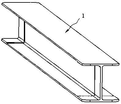
[0035] The present embodiment provides a method for making a soft mold for forming an I-beam composite material part, comprising the following steps:

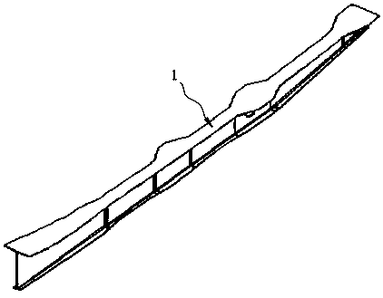
[0036] 1) Making dummy parts and molds: Process a set of I-beam metal dummy parts 2 that are exactly the same in size as the I-beam composite material part 1 by means of mechanical manufacturing, and at the same time make a set of soft molds for making soft molds Forming mold 3, the soft mold forming mold 3 includes an upper template 31 and a lower template 32, and the corresponding inner surfaces of the upper template 31 and the lower template 32 are all provided with cards matching the upper and lower sides of the I-beam metal dummy 2 Groove 4, so as to play a role of cooperation and limit during assembly, such as Figure 5 shown.

[0037] 2) Assembling and laying materials: Assemble the metal dummy part and the soft molding mold made in step 1) together according to the matching relationship, the two sides of the I-beam met...

Embodiment 2

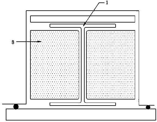
[0041] This embodiment provides a method for using a soft mold for forming an I-beam composite material part. The soft mold 5 made according to the method described in Embodiment 1 is used as a part of the forming mold for the I-beam composite material part 1, and is matched with the The soft mold forming mold 3 that is made completes the manufacturing process of manufacturing the I-beam composite material part 1, such as Figure 8 shown. The specific process is as follows:

[0042] First, two sets of preformed tooling are made, and the U-shaped components on both sides of the I-beam composite product are laid on the preformed tooling. After the paving is completed, the U-shaped component is peeled off from the preformed tooling and laid on Example 1. On the soft mold 5 used for forming the I-beam composite parts made in the above. While paving the U-shaped assembly, pave the top plate of the I-beam composite material part in the slot 4 of the upper template 31 of the soft m...


PUM


Abstract

The invention discloses a manufacturing method for a soft mode for I-beam composite material piece forming and application thereof. The open rubber soft mold is manufactured and is used for completingthe manufacturing process of an I-beam composite material structure piece. The soft mold manufacturing process is simple, the cycle is short, and the cost of raw materials is low. The I-beam composite material piece formed by the soft mold can uniformly and accurately transmit pressure applied by an autoclave, the phenomenon of overproof thickness of the composite material piece is avoided, the molding quality of the piece is ensured, and the production qualification rate and efficiency and the profile and dimensional accuracy after piece forming are improved. In addition, compared with a traditional air nozzle structure, the soft mode has lower air tightness requirements, longer service life and higher reliability, the soft mode is relatively simple and convenient in field use and latermaintenance, and the good using values are achieved.

Description

technical field [0001] The invention relates to a method for making a soft mold for forming I-beam composite material parts and its application. Background technique [0002] Resin-based carbon fiber composite materials have superior properties such as specific strength and specific stiffness, strong designability, good fatigue fracture resistance, corrosion resistance, and good dimensional stability. They are currently widely used in aviation, aerospace, transportation and other fields. High-performance structural materials. Among various carbon fiber composite molding processes, the autoclave process has uniform molding temperature and pressure, and has good adaptability to parts of different materials, shapes, sizes and structures. One of the main process methods of material components. [0003] The I-beam structure is a relatively common reinforced structure in composite material parts. It is usually divided into structural forms such as constant-section I-beams and va...

Claims


Application Information

Patent Timeline
Patent Type & Authority Applications(China)
IPC IPC(8): B29C70/34B29C70/78
CPCB29C70/342B29C70/78
Inventor 宋宏翔郭渊马秀菊任慧敏黎玉钦华文龙
Owner 航天海鹰(镇江)特种材料有限公司
Why Eureka
Try Eureka