Transverse conveying auger for a harvesting head

a technology of transverse conveying and harvesting head, which is applied in the direction of mowers, agricultural tools and machines, mowers, etc., can solve the problems of undesirable crop back-up, higher load on the outside of the intake channel of the harvesting machine,

Inactive Publication Date: 2005-05-26
DEERE & CO
View PDF9 Cites 23 Cited by
  • Summary
  • Abstract
  • Description
  • Claims
  • Application Information

AI Technical Summary

Benefits of technology

[0007] The center end disk prevents the crop from accumulating in the center of the intake channel of the harvesting machine, since the harvested crop is delivered separately on the left and right sides of the intake channel. The harvested crop accumulates on either side of the central end disk such that significant portions of the harvested crop are delivered to the intake channel of the harvesting machine a certain distance from the end disk. This makes the delivery of the crop to the harvesting machine uniform. In addition, the end disk prevents the crop from becoming attached to the ends of the flutes.

Problems solved by technology

The intake channel of the harvesting machine consequently is subjected to higher loads on the outside in many instances.
If plants are placed or wound around the terminal edge of the flutes, an undesirable crop back-up may occur, for example, in corn pickers that are operated in a mode in which a significant quantity of plant material is taken in addition to the corn ears.

Method used


Image

  • Transverse conveying auger for a harvesting head
  • Transverse conveying auger for a harvesting head
  • Transverse conveying auger for a harvesting head

Examples


Embodiment Construction

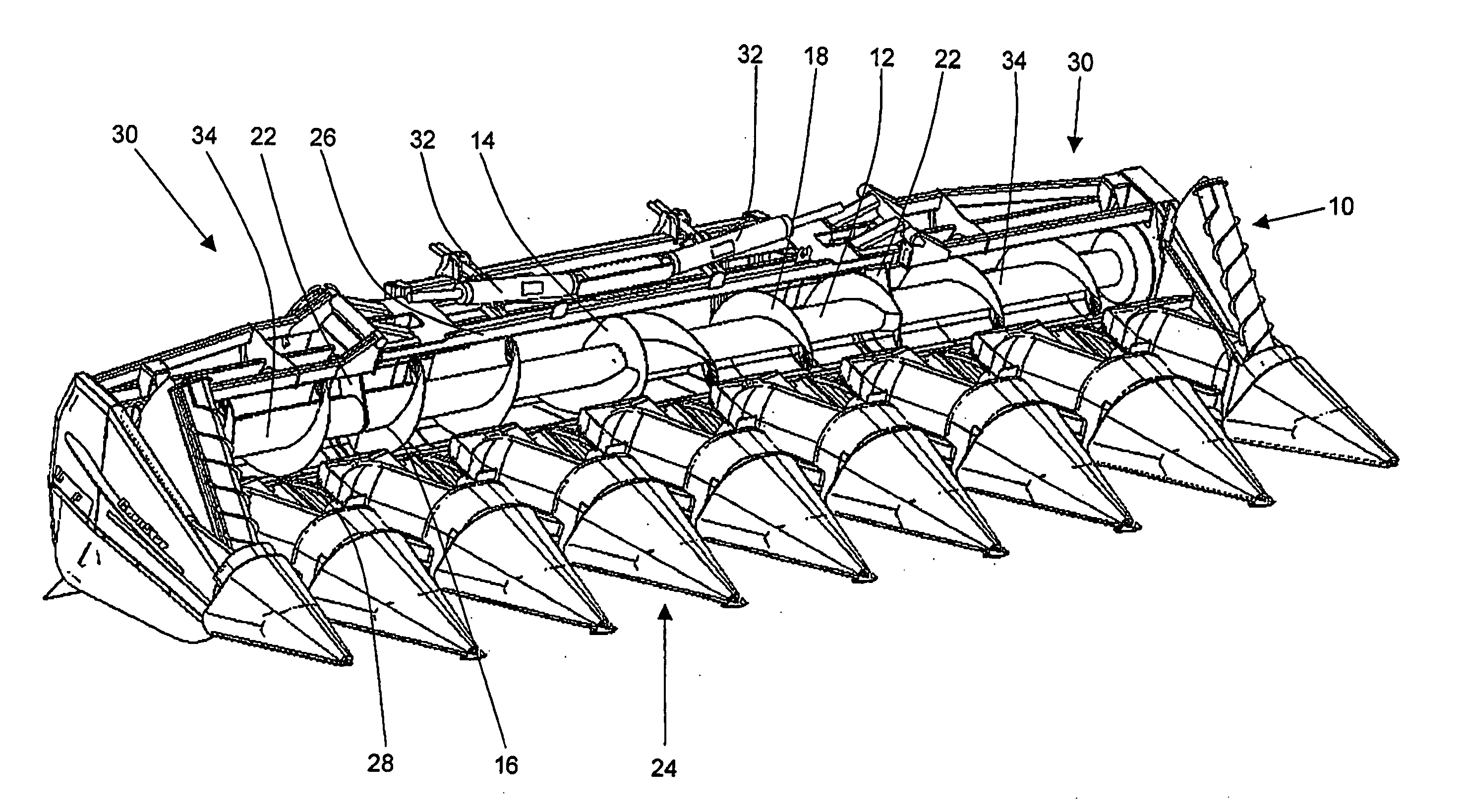
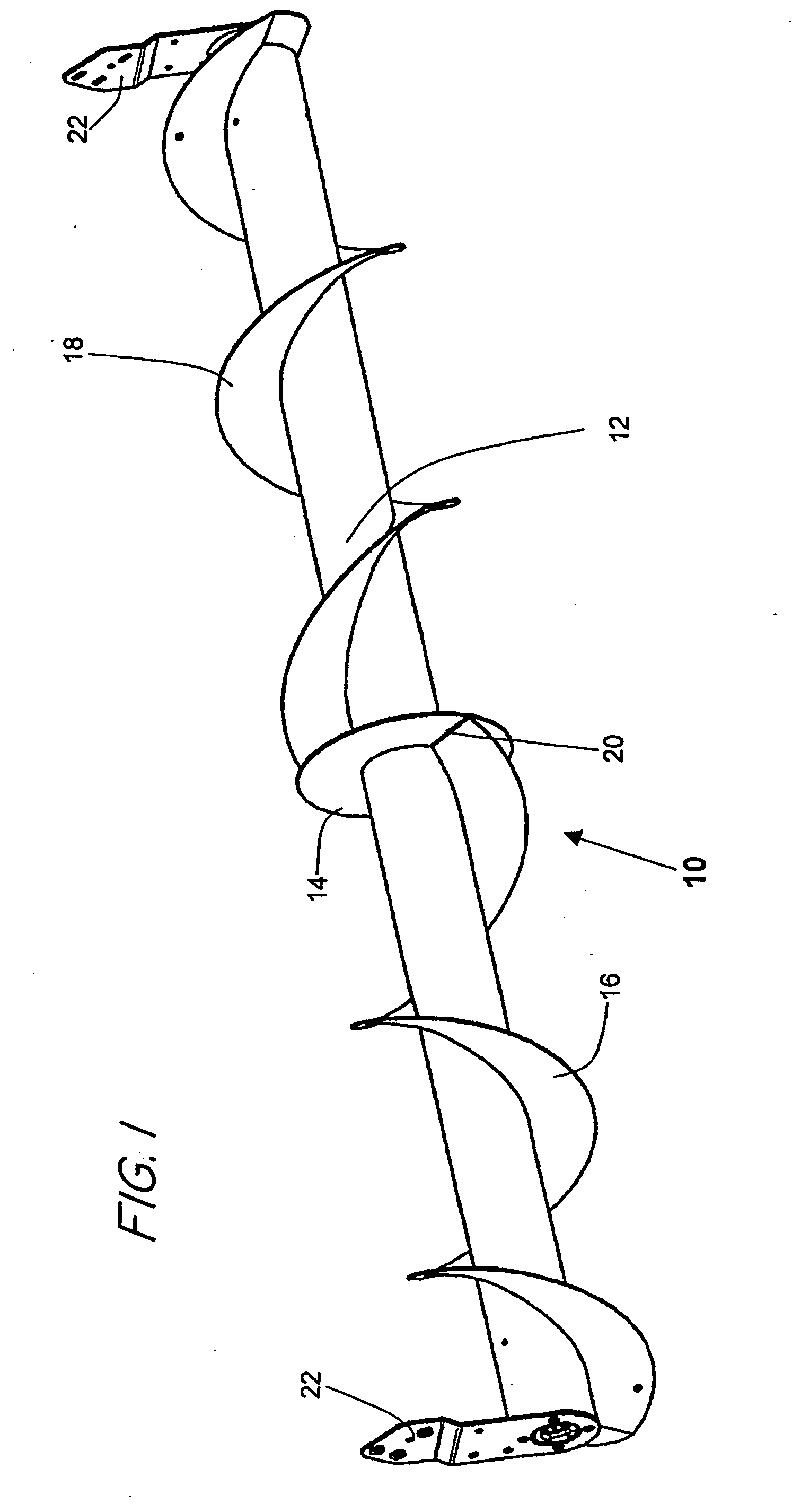
[0014] The transverse conveying auger 10 shown in FIG. 1 includes a tubular body 12 in the form of a circular cylinder, a centrally arranged annular end disk 14 that extends orthogonally relative to the longitudinal axis of the body 12 and two spiral-shaped flutes 16,18. Each of the flutes 16,18 extends helically from one outer end of the transverse conveying auger 10 to the end disk 14 arranged in the center of the body 12. Each of the flutes 16,18 is connected to the end disk 14 at an edge 20 that extends radially relative to the body 12 and is fixed at this location by means of a continuous weld. The outside diameter of the flutes 16 is constant over the length of the body 12 and corresponds to the outside diameter of the end disk 14. Brackets 22 for mounting the transverse conveying auger 10 on the frame of a harvesting head are provided on the ends of the body 12.

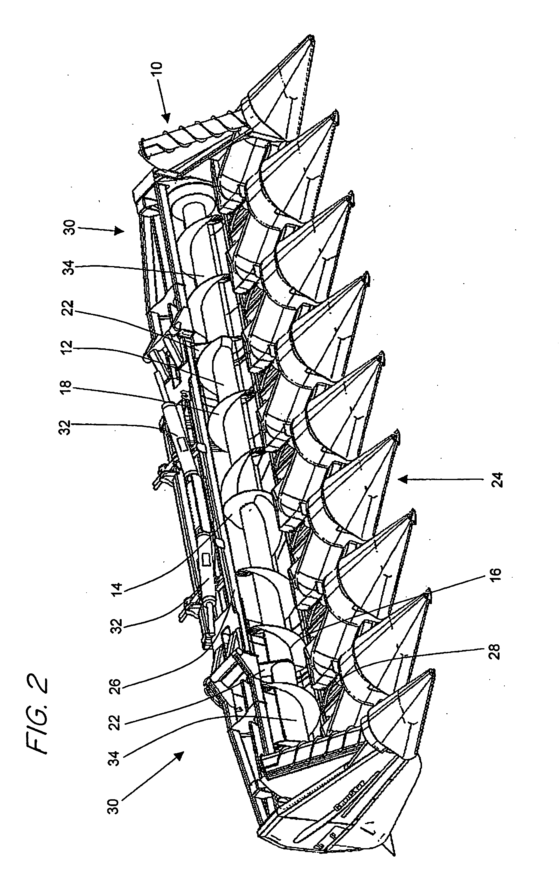
[0015]FIG. 2 shows a harvesting head 24 in the form of a corn plucker with a transverse conveying auger 10 accordin...


PUM


Abstract

A transverse conveying auger includes a tubular body and spiral-shaped flutes provided around the body. The flutes extend from the respective outer ends of the body to the center of the body. At the center of the tubular body, a center end disk is provided, to which the respective flutes are connected.

Description

FIELD OF THE INVENTION [0001] The present invention is directed to a transverse conveying auger for a harvesting head for agricultural crops. The auger has a tubular body and spiral-shaped flutes extending from the outer ends of the body toward the center. A center end disk is approximately perpendicular to the longitudinal axis of the body. BACKGROUND OF THE INVENTION [0002] When harvesting plants with agricultural harvesting machines, it is common practice to initially pick the crop to be harvested from the ground (for example, with the tines of a pick-up) or to cut the crop (e.g., by means of the cutter bar of a cutting attachment or mowing and intake devices of a corn picker or mowing and picking or plucking devices of a corn picker or plucker). The plants or crops separated therefrom, e.g., corn ears, are then conveyed in transversely converging fashion and sent to the intake channel or inclined conveyor of the harvesting machine. The lateral conveyance is realized with a trans...

Claims


Application Information

Patent Timeline
Patent Type & Authority Applications(United States)
IPC IPC(8): A01D43/08A01D57/22A01D61/00
CPCA01D57/22A01D43/082
Inventor WOLTERS, NORBERTRICKERT, CLEMENS
Owner DEERE & CO
Why Eureka
Try Eureka