
Handle fixing structure of vacuum cleaner

A vacuum cleaner and a fixed structure technology, applied in the direction of the handle, etc., can solve the problems that the handle 30 cannot be firmly fixed, the user cannot adjust the handle 30, and the length of the handle 30 cannot be adjusted

Inactive Publication Date: 2006-05-10
LG ELECTRONICS (TIANJIN) APPLIANCES CO LTD
View PDF0 Cites 2 Cited by
  • Summary
  • Abstract
  • Description
  • Claims
  • Application Information

AI Technical Summary

Problems solved by technology

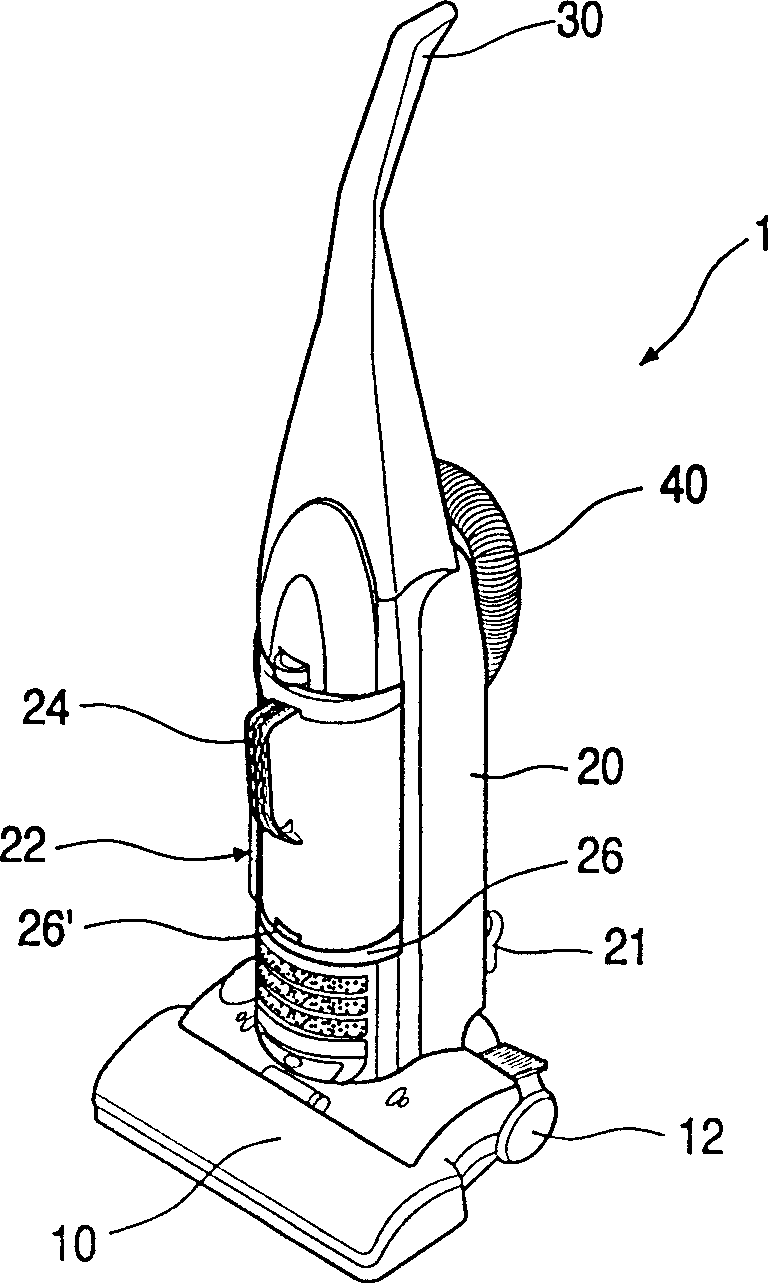
However, the vacuum cleaner structure of the prior art has the following disadvantages: the length of the handle 30 on the top of the fuselage 20 cannot be adjusted, so the user cannot adjust the length of the handle 30 according to his own height; On, the handle 30 cannot be firmly fixed on the fuselage 20

Method used


Image

  • Handle fixing structure of vacuum cleaner
  • Handle fixing structure of vacuum cleaner
  • Handle fixing structure of vacuum cleaner

Examples


Embodiment Construction

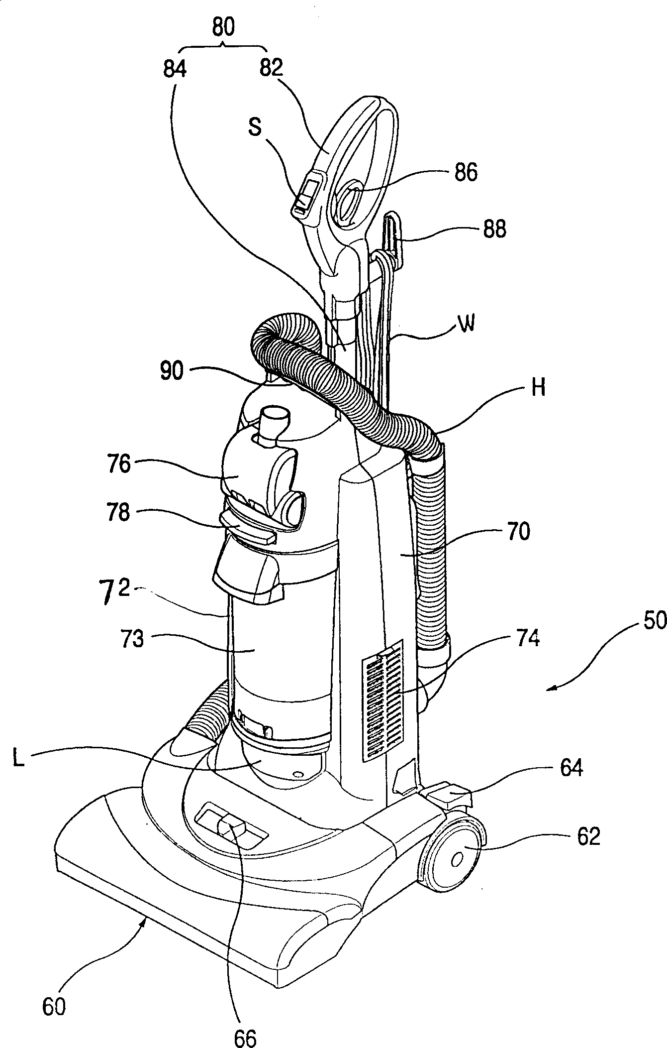
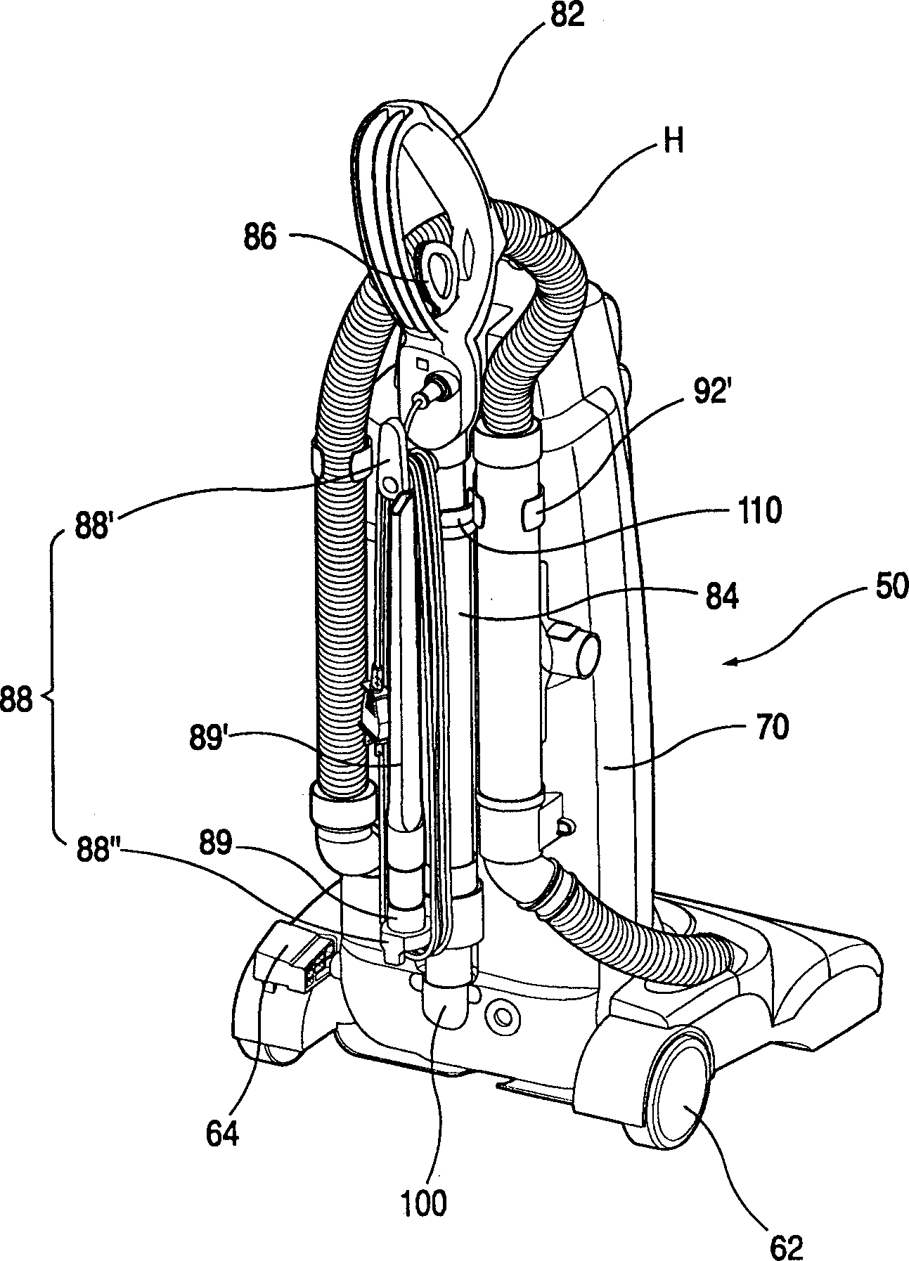
[0023] Such as figure 2 , 3 , 4, the upright vacuum cleaner 50 includes a suction head 60, a body 70 and a handle 80. Among them, the suction head 60 sucks air containing foreign matter while moving on the ground; the body 70 has a built-in device for generating suction force for sucking air containing foreign matter through the suction head 60; the handle 80 is equipped on the upper part of the body 70 so that the user can Easy to hold. The suction head 60 moves in a state close to the ground and sucks air through a suction port (not shown) on the bottom surface. The suction port of the external air main passage is formed on the bottom surface of the suction head 60 to guide the inflow of external air. In order to move the suction head 60 easily, moving wheels 62 are generally provided on both sides of the suction head 60 . The connecting portion of the suction head 60 and the body 70 forms a structure that can make the body 70 rotate within a certain angle range. Both ...


PUM


Abstract

The invention discloses a fixing device for fixing the handle pipe with adjustable length on the vacuum dust-collector tightly, which comprises a casing inside which several elements are mounted to filter the foreign matters of air; a handle mounted on one side of machine with a handle pipe whose length can be adjustable; a fixing plug for fixing the handle pipe on the machine with snail. The fixing plug has a pipe connection part to connect the handle pipe and a connection guide part for guiding fixing plug to connect the machine, wherein, the connection guide part is fixed on the machine via snail to fix the handle pipe more tightly on the machine.

Description

technical field [0001] The invention belongs to a device of a vacuum cleaner, in particular to a handle fixing structure of a vacuum cleaner which enables an adjustable-length handle pipe to be more firmly fixed on a machine body. Background technique [0002] Such as figure 1 As shown, the upright vacuum cleaner 1 includes a suction head 10 , a body 20 and a handle 30 . Wherein, the suction head 10 sucks air containing foreign matter while moving on the ground; The suction head 10 moves close to the ground and sucks air through a suction port (not shown) on the bottom surface, and the suction head 10 is equipped with a pair of moving wheels 12 for easily moving the suction head 10 . The back of fuselage 20 also has line hook 21, and line hook 21 is mutually symmetrically formed in pairs at upper and lower ends of body 20 back respectively, and a pair of line hook 21 winds power line (not shown). Components such as a motor (not shown) and a suction fan (not shown) for gen...

Claims


Application Information

Patent Timeline
IPC IPC(8): A47L9/32
Inventor 白相木
Owner LG ELECTRONICS (TIANJIN) APPLIANCES CO LTD
Learn More