
Bidirectional drive disc brake

A two-way drive and disc brake technology, applied to bicycle brakes, bicycle accessories, etc., can solve the problems of different degrees of wear, increase the consumption of manpower or electric energy, affect the durability of disc brakes, etc., and achieve the effect of eliminating axial force

Inactive Publication Date: 2006-05-10
许艳
View PDF0 Cites 8 Cited by
  • Summary
  • Abstract
  • Description
  • Claims
  • Application Information

AI Technical Summary

Problems solved by technology

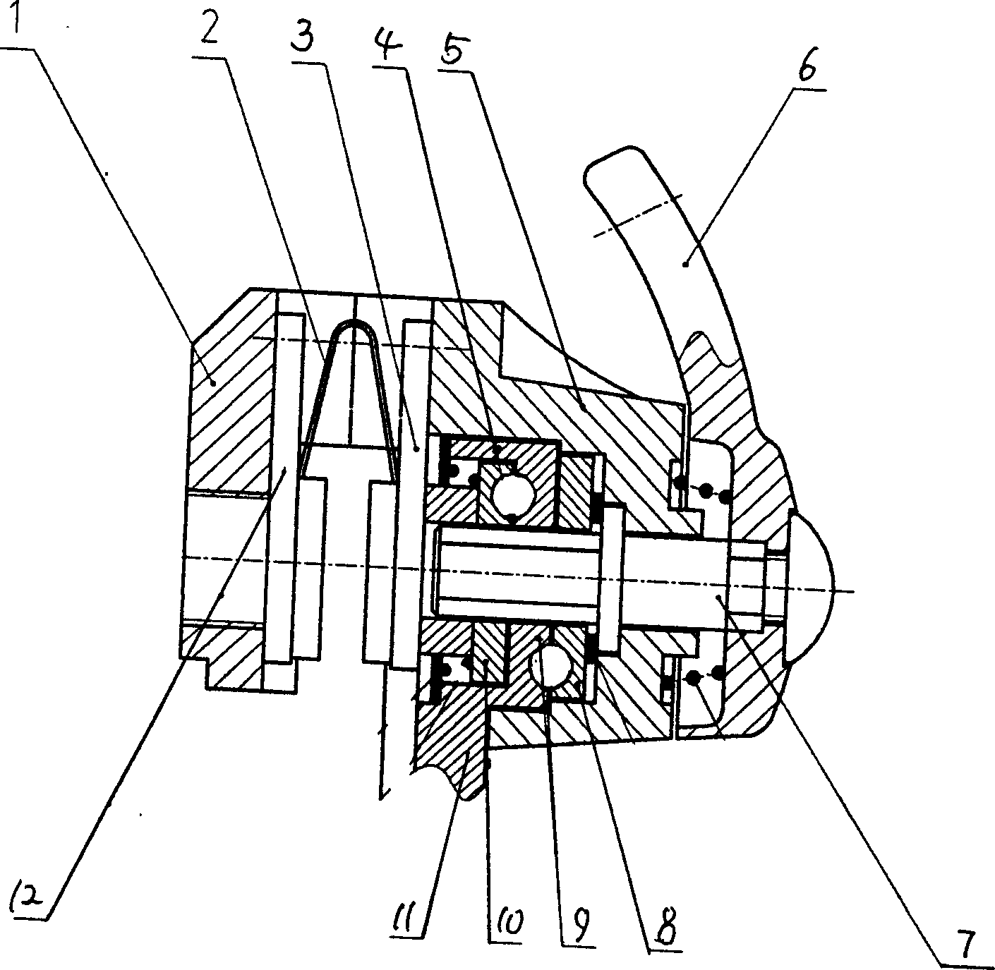
Therefore, the outstanding problem reflected at present is: the two friction plates do not contact the disc at the same time at the moment before braking, but under the drive of the one-way drive disc, one friction plate is first pressed on the end surface of the disc, and then the disc is driven by the one-way drive. Under the force of the disk, the disk is forced to produce elastic deformation or under the force of the disk's own stiffness to overcome the force of the floating return spring in the floating bracket to displace the caliper in the axial direction until it contacts the friction plate on the other side. brake
When people ride bicycles or electric bicycles, they will increase the consumption of manpower or electric energy. In addition, because the two friction plates are not in contact with the disc at the same time when the driving device brakes, the wear degree of the two friction plates is different, which affects the durability of the disc brake.

Method used


Image

  • Bidirectional drive disc brake
  • Bidirectional drive disc brake
  • Bidirectional drive disc brake

Examples


Embodiment 1

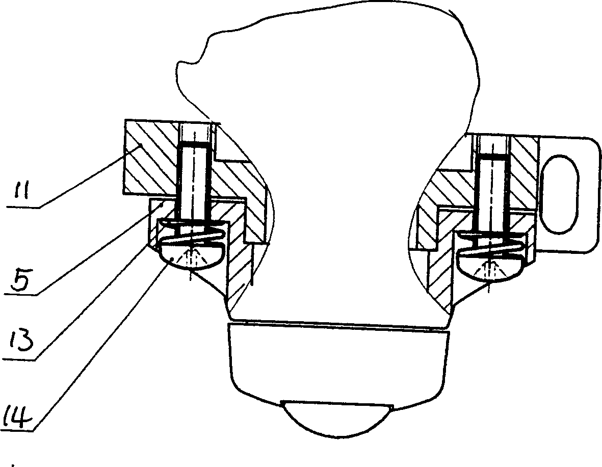
[0017] Embodiment 1, the two-way drive disc brake shown in Figure 1 and Figure 2 includes a disc brake disc and a brake caliper. 3-piece assembly, a V-shaped return leaf spring 2 is arranged between the two friction plate assemblies 12 and 3, one of the friction plate assemblies 12 is installed in the clamp arm 1, and the other friction plate assembly 3 is connected to the driving device, and the driving device The housing 5 and the pincer arm 1 are fixedly connected as one, and a fixed support frame 11 is provided at the jaw on one side of the driving device. The bosses 4 that slide and cooperate with each other, the bosses 4 are circular, cooperate with the inner cavity of the housing 5 to achieve center positioning, and can slide in the axial direction. In order to prevent relative rotation between the fixed support frame 11 and the housing 5, a limiting device is provided between the fixed supporting frame 11 and the housing 5, and the limiting device can adopt a structure...

Embodiment 2

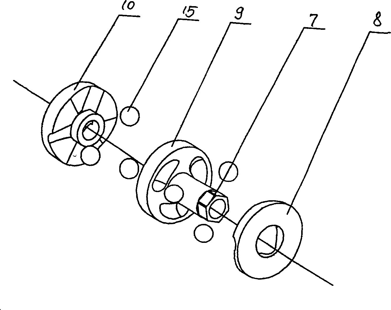
[0018] Embodiment 2, as shown in Figure 2, the inner surface of the casing 5 connected with the driving device is die-cast with a ball socket for accommodating steel balls 15, then the inner surface of the casing 5 forms a moving disk 8 that cooperates with the fixed disk 9, and the driving shaft 7 is connected to the fixed disk 9. Fixed disk 9 is connected to drive. This saves a moving disc part and reduces the overall volume of the disc brake caliper.

Embodiment 3

[0019] Embodiment 3, as shown in Figure 3, the drive shaft 7 is connected and driven with the fixed plate 9, and the disk surfaces of the two moving plates 8 and 10 are provided with 2 to 3 helical surfaces or spiral grooves corresponding to the surface of the fixed plate 9, and the fixed plate Steel ball 15 is housed between 9 and moving plate 8,10.


PUM


Abstract

Disclosed a bidirectional driving disc brake comprises a disc-brake disc and a brake clamper. Wherein, the two sides of jaw of brake clamper have left and right friction plates while one friction plate is inside the clamp arm, and another one is connected to the driving device; a fixed support holder is mounted on the jaw which is on the side of driving device, and its has a projected table for supporting the inner chamber of casing of driving device and sliding matched with said casing; the driving device has three driving discs and one driving shaft while the driving shaft is drawn by the brake tight-wire to rotate the static disc or rotate two movable discs at one time; the discs can realize axial driving via the spiral surface or spiral slots arranged on disc surface and the relative rotation of steel ball; and said two movable discs are individually rigidly connected to the casing of driving device and friction plates. The invention utilizes the bidirectional driving theory of driving disc to make said two friction plates close to the disc at one time in the brake process of disc brake and clamp the disc.

Description

technical field [0001] The invention relates to a brake device for bicycles, tricycles and light power vehicles, in particular to a disc brake with a bidirectional drive structure. Background technique [0002] The disc brake includes a brake caliper body and a brake disc. The brake caliper body is equipped with a driving device and a friction plate, which are fixedly connected to the corresponding position of the vehicle frame, and the brake disc is fixedly installed on the wheel hub. At present, in various mechanical disc brake products at home and abroad, the driving device in the brake caliper body mostly adopts a one-way drive structure due to the small effective space between the spokes of the wheel and the disc brake disc. The spiral curved surface on the end face drives the friction plate and the brake disc tightly to achieve braking. Therefore, the outstanding problem reflected at present is: the two friction plates do not contact the disc at ...

Claims


Application Information

Patent Timeline
IPC IPC(8): B62L1/02
Inventor 许艳
Owner 许艳
Learn More