Differential gearing

A transmission device and transmission system technology, applied in the direction of differential transmission device, transmission device, control device, etc., can solve the problems affecting the speed difference and achieve the effect of small rotating mass

Inactive Publication Date: 2009-10-14
MAGNA POWERTRAIN AG & CO KG
View PDF1 Cites 5 Cited by
  • Summary
  • Abstract
  • Description
  • Claims
  • Application Information

AI Technical Summary

Problems solved by technology

A pure differential cannot effectively affect the speed difference that exists

Method used


Image

  • Differential gearing
  • Differential gearing
  • Differential gearing

Examples


Embodiment Construction

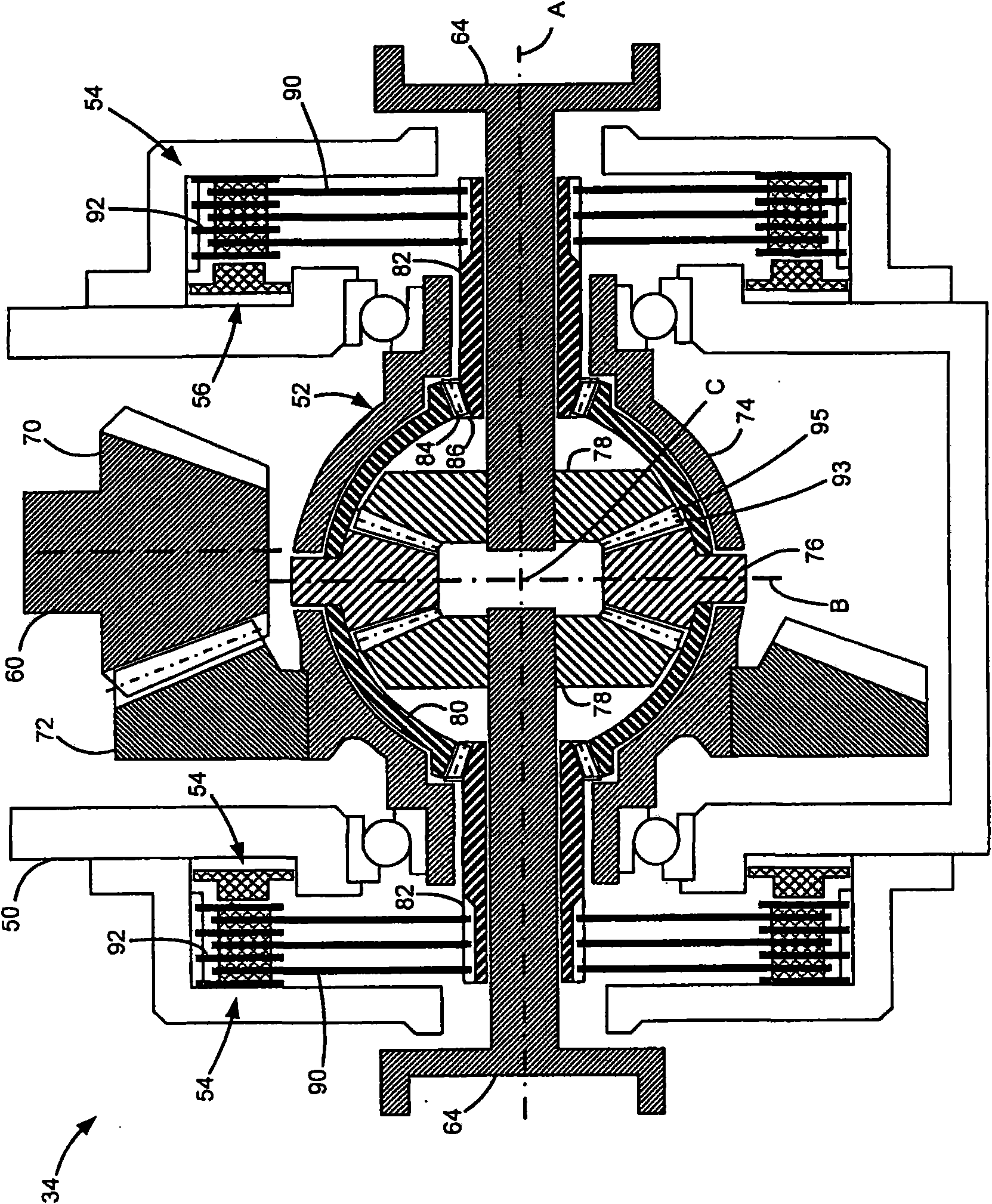
[0035] exist figure 1 An exemplary motor vehicle powertrain 10 is schematically shown in FIG. 2 , including a transmission 12 having a force transmission path 16 , an engine 18 and a transmission 20 . The force transmission path 16 includes a cardan shaft 28 driven through a transmission 20 , a pair of shafts 30 connected to a pair of wheels 32 , and a main drive 34 effective to transmit drive torque from the cardan shaft 28 to one or both shafts 30 . Although a vehicle driveline with rear drive is shown here by way of example, the invention can of course also be used in a vehicle driveline with front-wheel drive or all-wheel drive.

[0036] In order to achieve so-called "torque vectoring" driving (TV driving) and / or differential locking driving, the control unit 40 controls the operation of the main transmission 34 on the basis of a number of vehicle parameters. The control unit 40 is electronically connected to at least one sensor, preferably a plurality of sensors. Exemp...


PUM


Abstract

A transmission has a rotatable differential cage (74) and two output shafts (64). In order to distribute a torque between the output shafts (64), at least one balancing wheel (76) is rotatably mounted on the differential cage (74), which balancing wheel (76) is drive-coupled to a respective drive wheel (78) of the output shafts (64). The gearing also has at least one concavely curved coupling wheel (80) which is drive-coupled firstly to at least one of the drive wheels (78) and secondly to at least one hollow shaft (82). The hollow shaft (82) surrounds one of the output shafts (64). The hollow shaft (82) can be braked or driven relative to a part of the gearing.

Description

technical field [0001] The invention relates to a transmission for a motor vehicle with a rotatable differential carrier and two output shafts, wherein the differential carrier is rotatable in order to distribute the torque between the output shafts At least one balance wheel, which is drive-coupled to a respective drive wheel of the output shaft, is arranged in a fixed manner. Background technique [0002] So-called "active-yaw" or "torque vectoring" (TV) systems are known for modern drive trains, for example all-wheel drive trains. The yaw rate of the vehicle is effectively controlled by the TV system, where the transmission torque will be unevenly distributed on the wheels. In this way, for example, more transmission torque can be transferred to the outer cam, so that under normal driving conditions the behavior of the overcontrol can be adjusted. [0003] Differential transmissions with optionally activatable differential locks are also known in order to suppress the s...

Claims


Application Information

Patent Timeline
Patent Type & Authority Applications(China)
IPC IPC(8): B60K23/04B60K23/08F16H48/30
CPCB60K23/04F16H48/30F16H48/22F16H48/11F16H2048/204F16H2048/085F16H48/08F16H48/24
Inventor 曼弗雷德·拉姆
Owner MAGNA POWERTRAIN AG & CO KG
Why Eureka
Try Eureka