
Chamfering and deburring device

A deburring and chamfering technology, which is applied to gear teeth manufacturing devices, gear teeth, worm gears, etc., can solve the problems of simultaneous gear shaving and inability to hob and shave, and achieve the effect of improving hobbing processing efficiency and processing efficiency

Active Publication Date: 2021-08-27
浙江陀曼智能科技股份有限公司
View PDF6 Cites 0 Cited by
  • Summary
  • Abstract
  • Description
  • Claims
  • Application Information

AI Technical Summary

Problems solved by technology

[0006] The purpose of the present invention is to provide a chamfering and deburring device to solve the problem that the hobbing and shaving cannot be performed simultaneously in the background technology

Method used

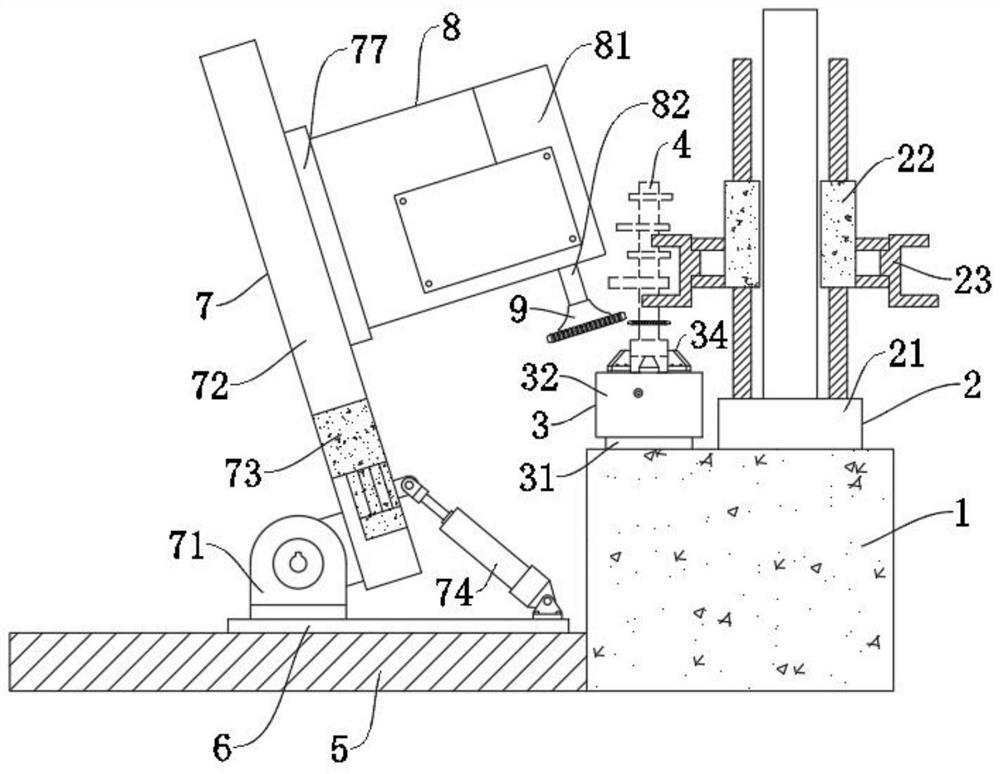
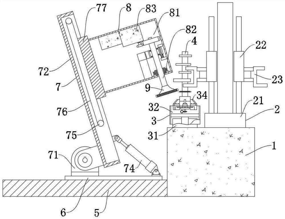
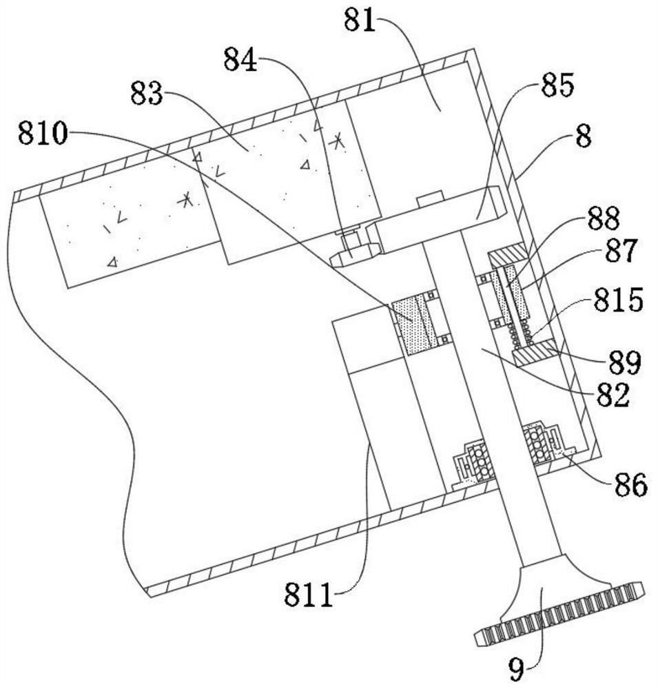

Image

  • Chamfering and deburring device
  • Chamfering and deburring device
  • Chamfering and deburring device

Examples


Embodiment Construction

[0027] The following will clearly and completely describe the technical solutions in the embodiments of the present invention with reference to the accompanying drawings in the embodiments of the present invention. Obviously, the described embodiments are only some, not all, embodiments of the present invention. Based on the embodiments of the present invention, all other embodiments obtained by persons of ordinary skill in the art without making creative efforts belong to the protection scope of the present invention.

[0028] see Figure 1-7 , an embodiment provided by the present invention: a chamfering and deburring device, including a base 1, a workpiece 4, a first linear slide 5 and a hobbing cutter 9, the upper surface of the base 1 is provided with a workpiece fixture 2 and The workpiece fixing component 3, the upper surface of the first linear slide table 5 is slidably connected with the sliding seat 6, the upper surface of the sliding seat 6 is provided with a suppor...


PUM


Abstract

The invention relates to the technical field of numerical control gear hobbing machines, in particular to a chamfering and deburring device. The chamfering and deburring device comprises a base, a workpiece, a first linear sliding table and a hobbing cutter, wherein the upper surface of the base is provided with a workpiece clamp and a workpiece fixing assembly, the upper surface of the first linear sliding table is slidably connected with a sliding seat, the upper surface of the sliding seat is provided with a supporting assembly, the supporting assembly comprises a supporting seat, the bottom end of the supporting seat is connected and fixed to the sliding seat through a screw, the end, away from the sliding seat, of the supporting seat is rotationally connected with a second linear sliding table through a rotating shaft, the side, away from the supporting seat, of the second linear sliding table is movably connected with a first hydraulic oil cylinder and a connecting seat, and the end, away from the second linear sliding table, of the first hydraulic oil cylinder is rotationally connected with the upper surface of the sliding seat through a hinge shaft. According to the chamfering and deburring device, hobbing and shaving are combined, the hobbing action and the shaving action are carried out at the same time, and chamfering operation is directly carried out in the later period of machining, so that the machining efficiency is improved.

Description

technical field [0001] The invention relates to the technical field of numerically controlled gear hobbing machines, in particular to a chamfering and deburring device. Background technique [0002] Worm gears are commonly used to transmit motion and power between two interleaved shafts. The worm gear and the worm are equivalent to the gear and the rack in their middle plane, and the worm is similar in shape to the screw. [0003] The characteristic of the worm gear structure is that it can obtain a large transmission ratio, which is more compact than the crossed-axis helical gear mechanism. The meshing tooth surfaces of the two wheels are in line contact, and its load capacity is much higher than that of the crossed-axis helical gear mechanism. Wide range of applications. [0004] Combined turbine is a kind of turbine, which is characterized by integrated processing of turbine and shaft, or integrated processing of two or more turbines on the shaft. The processing of this...

Claims


Application Information

Patent Timeline
Patent Type & Authority Applications(China)
IPC IPC(8): B23F11/00B23F19/10B23F23/06B23F23/12
CPCB23F11/00B23F19/104B23F23/06B23F23/12B23F23/1237
Inventor 周鉴张凌
Owner 浙江陀曼智能科技股份有限公司
Learn More