Supercharge Your Innovation With Domain-Expert AI Agents!

Air attemperation apparatus

A kind of air conditioning technology, applied in the field of air conditioning devices

Inactive Publication Date: 2006-05-10
HITACHI APPLIANCES INC
View PDF1 Cites 2 Cited by
  • Summary
  • Abstract
  • Description
  • Claims
  • Application Information

AI Technical Summary

Problems solved by technology

However, since the control is not performed according to the state of the actual refrigeration cycle, it cannot respond to individual differences in the adjusted decompression amount of the decompression unit or changes in the flow resistance value due to accumulation of garbage, etc. Therefore, decompression may occur The amount of depressurization in the unit is not necessarily the optimum gas injection condition

Method used


Image

  • Air attemperation apparatus
  • Air attemperation apparatus
  • Air attemperation apparatus

Examples


Embodiment Construction

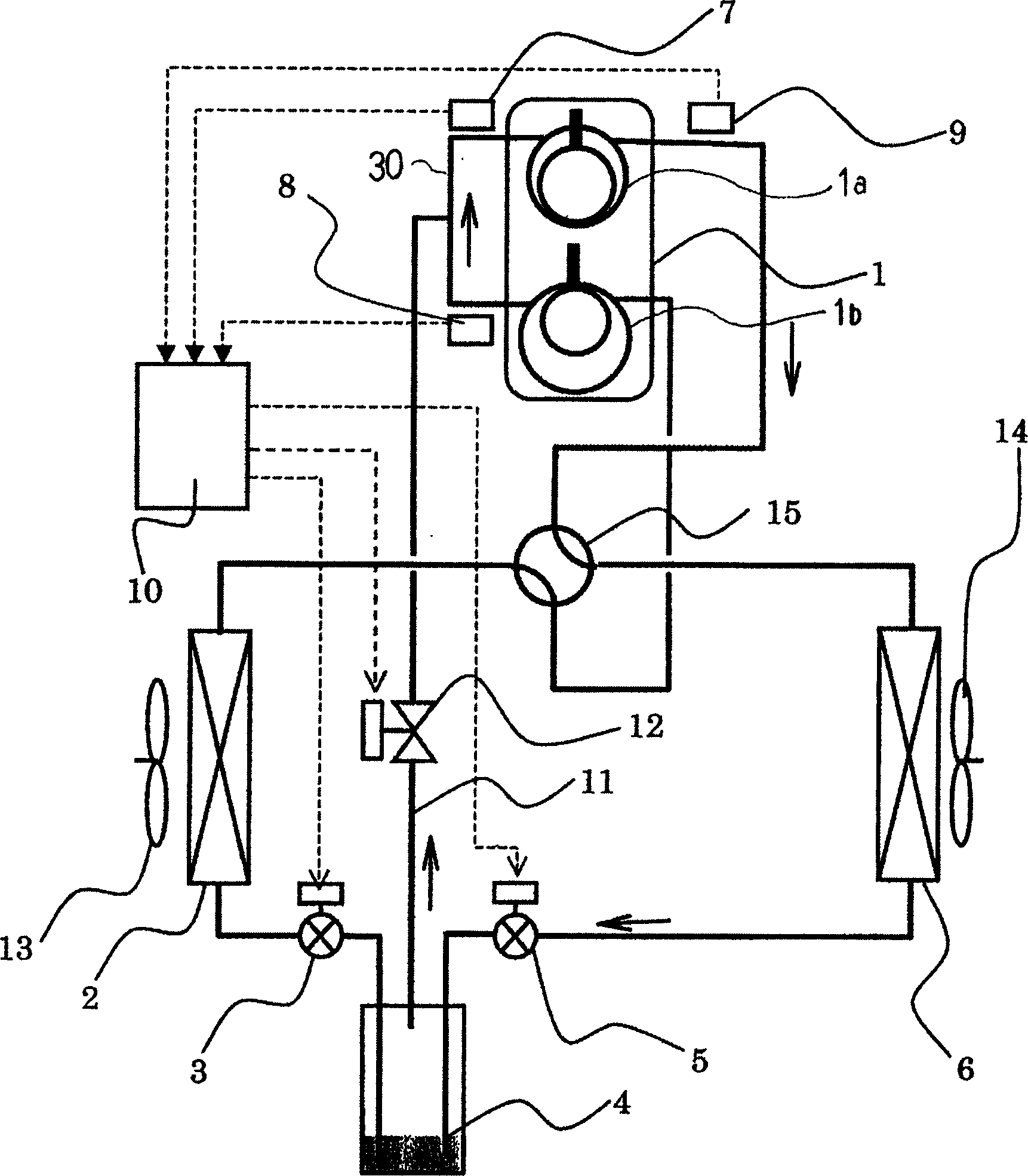
[0021] Hereinafter, an embodiment of the present invention will be described in detail with reference to the drawings. figure 1 It is a refrigerating cycle in an air-conditioning device with gas injection, and indicates the direction of refrigerant flow during heating operation. The two-stage compressor 1 is a compressor having two compression sections on a high-stage side (high-pressure side compressor section) 1a and a low-stage side (low-stage side compressor section) 1b, details of which will be described later. The outdoor heat exchanger 2 as the first heat exchanger functions as an evaporator during the heating operation (and as a condenser during the cooling operation). The second electric expansion valve 5 is a decompression unit with a variable decompression amount provided upstream in the refrigerant flow direction (downstream during air-cooling operation). The first electric expansion valve 3 is a decompression means with a variable decompression amount located dow...


PUM


Abstract

Provided is an air conditioner in which refrigerant is sprayed from a gas-liquid separator (4) to the refrigerant outlet of a compressor (1) on a low-stage side compression part (1b), and passes through the gas-liquid separator (4) on the downstream side. Even if the resistance value of the pressure reducer changes due to individual differences in the decompression amount adjustment unit or accumulation of garbage, etc., optimal injection can be performed. According to the difference between the low-stage compressor discharge temperature (8) and the high-stage compressor suction temperature (7) of the two-stage compressor (1) having the low-stage compressor (1b) and the high-stage compressor (1a), , to determine the decompression amount of the decompression units (3, 5) on the downstream side of the gas-liquid separator (4).

Description

technical field [0001] The present invention relates to an air conditioning device and relates to gas injection. Background technique [0002] As a technology related to power saving of air conditioners, there is known a gas injection system that injects a gas refrigerant that does not contribute to evaporation during the compression process to reduce the compression power. That is, it has: a compressor; a refrigerant flow direction switching unit connected to the compressor to switch the refrigerant flow direction in cooling operation and heating operation; a first heat exchanger connected to the refrigerant flow direction switching unit; A decompression unit, which is connected to the first heat exchanger; a gas-liquid separator, which is connected to the first decompression unit; a second decompression unit, which is connected to the gas-liquid separator; a second heat exchanger, One side thereof is connected to the first decompression unit, and the other side is connect...

Claims


Application Information

Patent Timeline
IPC IPC(8): F25B1/10F25B1/04
CPCF25B2400/13F25B2400/23F25B2600/2509
Inventor 野中正之中村启夫太田和利樋爪达也
Owner HITACHI APPLIANCES INC
Features
  • R&D
  • Intellectual Property
  • Life Sciences
  • Materials
  • Tech Scout
  • Unparalleled Data Quality
  • Higher Quality Content
  • 60% Fewer Hallucinations
Learn More