Electric connector

A technology of electrical connectors and contacts, which is applied in the field of electrical connectors for differential transmission, can solve the problems of thin insulators, difficulty in integrating the positions of female contacts and thin insulators, poor processability, etc., and prevent deformation and bending , the effect of simple setting operation

Inactive Publication Date: 2006-05-10
HONDA TSUSHIN IND
View PDF2 Cites 17 Cited by
  • Summary
  • Abstract
  • Description
  • Claims
  • Application Information

AI Technical Summary

Problems solved by technology

[0012] In addition, as an integral molding method in the above-mentioned module housing, although a gasket of a thin insulator can be inserted between the mating terminals for secondary molding, the positional integration of the above-mentioned female contact and the thin insulator is difficult, and the insulator Very thin, poor processability

Method used


Image

  • Electric connector
  • Electric connector
  • Electric connector

Examples


Embodiment Construction

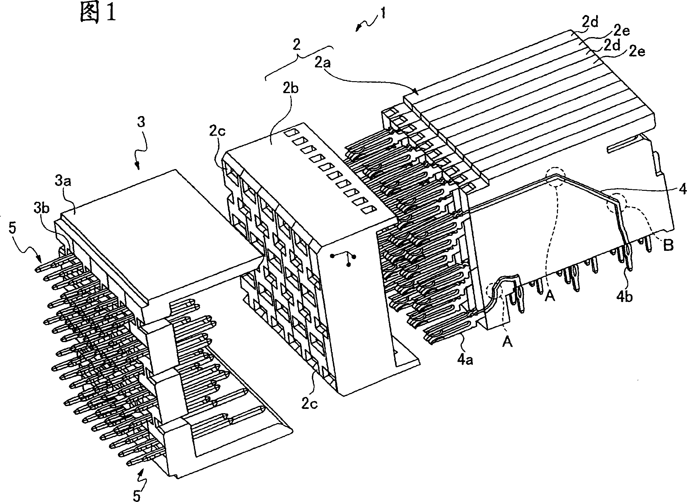
[0031] First, refer to Figure 1- Figure 8B The best mode for carrying out the present invention will be described. As shown in Fig. 1, the electrical connector 1 of the present invention is carried on the printed circuit board, one end of the contact is connected with the circuit, the other end of the contact forms the female mold connector 2 of the female mold connection part, and has The male contact point connected by the plug connector 2 is constituted by the backplane connector 3 arranged on the machine frame.

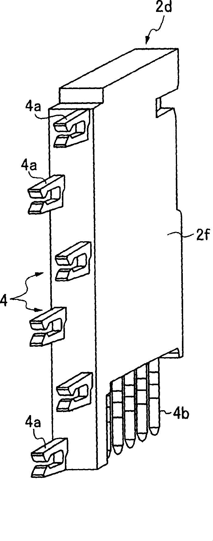
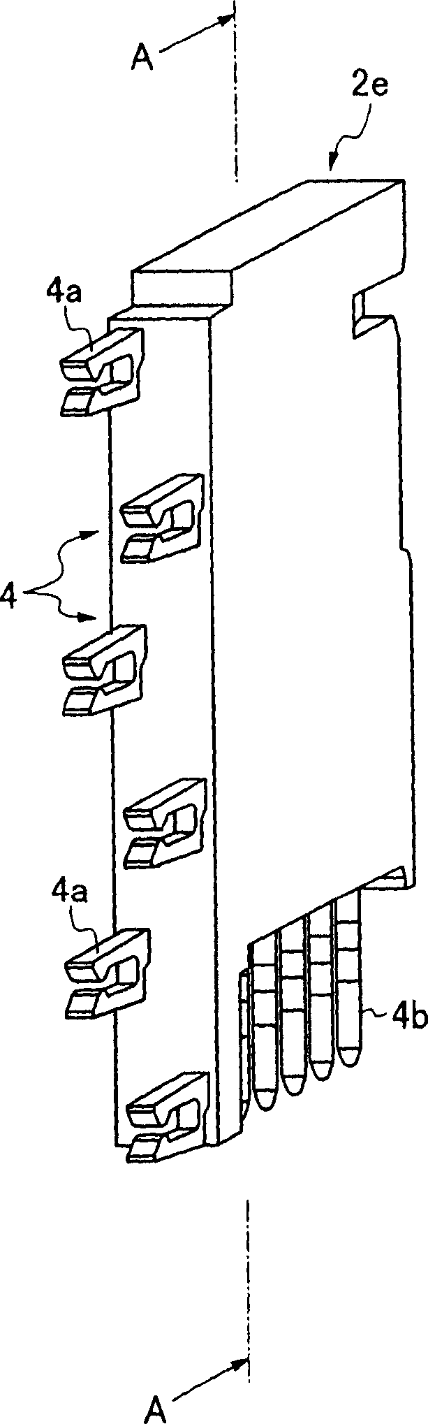
[0032] The plug connector 2 is composed of a joint housing 2b provided with a housing hole 2c for receiving the female connection part, a female contact housing 2a, and a female contact 4 formed into the female contact housing 2a by insert molding.

[0033] The coupling portion 4a of the female connection portion of the female contact 4 is accommodated in the receiving hole 2c as a mating terminal for transmitting an electrical signal. And the receiving holes 2...


PUM


Abstract

An electric connector for differential transmission principally transmitting a high-frequency electric signal where a ratio between the interval (a) between both signal terminals constituting a pair terminal being buried in a female contact housing and the interval (b) between the pair terminals is set ab. Since the both signal terminals are molded integrally while being buried separately in modular housings obtained by dividing the female contact housing along a vertical direction to match 1 / 2 of the interval (a) between both signal terminals, the interval (a) of both signal terminals can be kept small and in parallel. Consequently, crosstalk can be improved furthermore.

Description

technical field [0001] The invention is a connector (connector) used to connect printed circuit boards between computers, servers or backplane plug-ins and machines or printed circuit boards, and mainly relates to electrical connections for differential transmission of high-frequency electrical signals. device. Background technique [0002] As everyone knows, for many years, as the electrical connector 11 used on the high-speed transmission path, just as Figure 9 As shown, there is a housing 14 for female mold contacts that inserts molded female mold contacts 12a, 12b, and a joint housing 15 that is held by pressing the connecting portion of the above-mentioned contacts 12a, 12b into the receiving holes, and the above-mentioned female mold contacts are combined. The back plate connector 17 of the male contact 16 is formed. [0003] As is well known, as noise countermeasures for the above-mentioned electrical connector 11, a differential transmission method in which one sig...

Claims


Application Information

Patent Timeline
Patent Type & Authority Applications(China)
IPC IPC(8): H01R13/514H01R13/658
CPCH01R12/724H01R13/514H01R13/6461H01R13/6477H01R13/6586
Inventor 大西浩司松江诚彦
Owner HONDA TSUSHIN IND
Why Eureka
Try Eureka