Resistivity detector and resistivity detection apparatus
A detection device and detector technology, which is applied in the direction of measuring devices, accessory devices, fluid resistance measurement, etc., can solve problems such as difficult to find, difficult to visually detect element dirt, deviation, etc., so as to avoid forgetting to check and easy to check dirt Effect
- Summary
- Abstract
- Description
- Claims
- Application Information
AI Technical Summary
Problems solved by technology
Method used
Image
Examples
no. 1 Embodiment approach
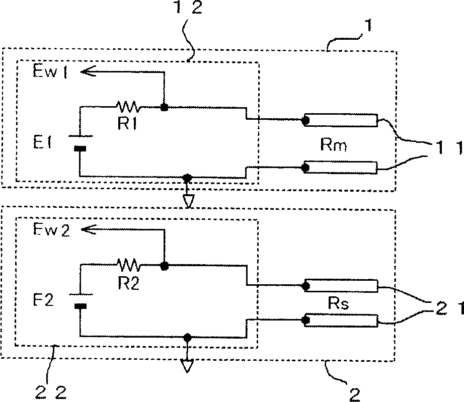
[0042] According to this embodiment, the specific resistance detector for detecting the specific resistance of a solution uses two detectors, a main detector and a sub detector, which detect different resistance values when measuring the resistance value of the same solution. here,
[0043] Assuming that the detection element of the main detector (hereinafter referred to as the main detection element) has no dirt attached to it, the resistance value of the solution between the main detection elements is R0 ... (1)
[0044] The resistance value of the solution between the sub-detection elements when the detection element (hereinafter referred to as the sub-detection element) of the sub-detector is not attached to dirt is R0 / χ. …(2)
[0045] In addition, when dirt is attached to both the main detection element and the sub-detection element, the resistance value of the dirt attached to each detection element is Rd. then,
[0046] When dirt is attached to the main detection ele...
no. 2 Embodiment approach
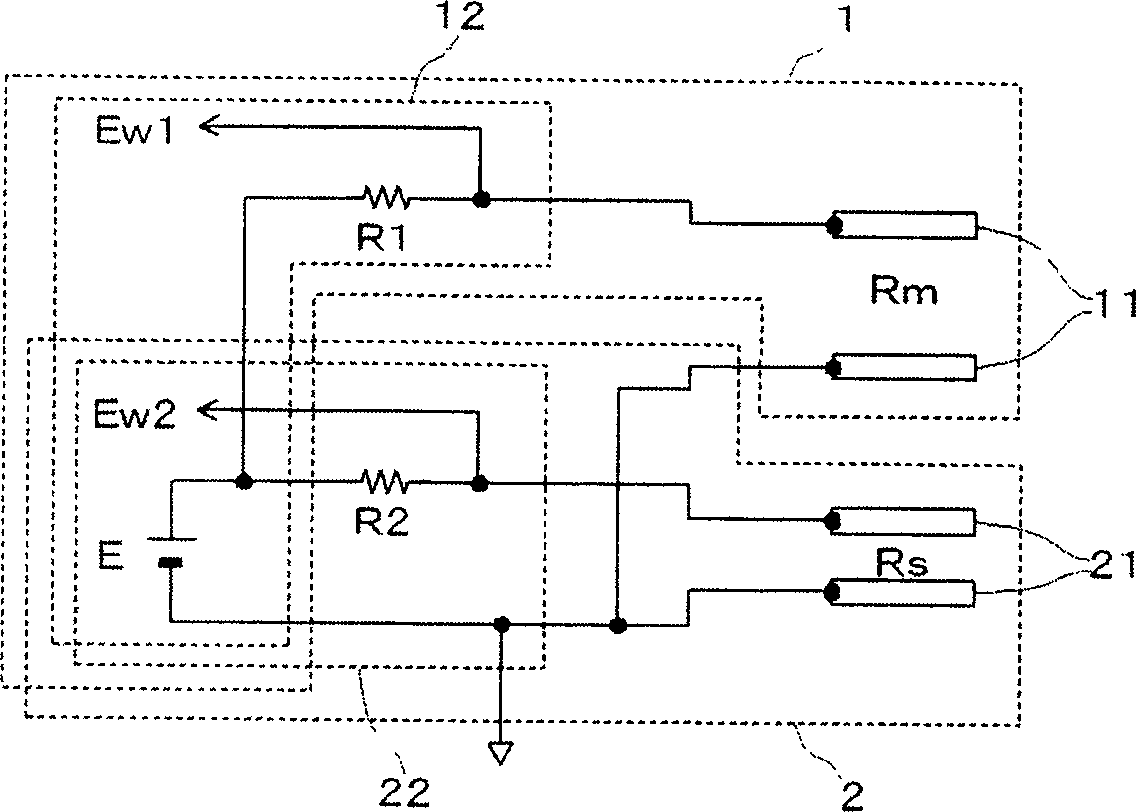
[0058] If the main detection element and the sub-detection element are arranged to be immersed in the same solution, since the main detection element and the sub-detection element are placed in the same environment, the degree of contamination of the two detection elements is the same. Therefore, in the above-mentioned first embodiment, the detection resistance values of the main and sub detectors are different (χ≠1) when the detection element is not stained as described above.
[0059] On the other hand, in the second embodiment, the detection resistance value between the main detectors and the detection resistance value between the sub detectors are set to be the same (χ = 1), and the difficulty of adhesion of dirt to the main detection element (the speed of dirt advancement) and the difficulty of adhesion of dirt to the sub-detection element (the speed of dirt advancement) are different.
[0060] On the surface of the object, dirt is easy to adhere to the rough side. The...
no. 3 Embodiment approach
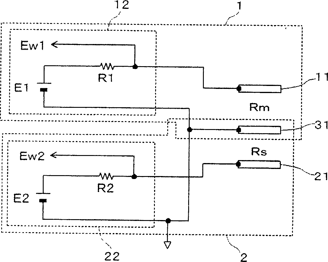
[0083] This embodiment corresponds to a combination of the first and second embodiments described above.
[0084] In this embodiment, when the main detector and the sub-detector are immersed in the same solution, when there is no dirt attached to the main detection element and the sub-detection element, the resistance value of the working fluid between the sub-detection elements is different from that of the main detection element. The resistance value of the machining fluid differs between detection elements. Furthermore, it is configured so that the difficulty of adhesion of dirt to the sub-detection element (the advancing speed of dirt) is different from the difficulty of adhesion of dirt to the main detecting element (the advancing speed of dirt).
[0085] Here, in the state where no dirt adheres to the main detection element and the sub-detection element,
[0086] Assume that the resistance value of the solution between the main detection elements is R0, ...(14)
[0087...
PUM
 Abstract
Description
Claims
Application Information
 - R&D
- Intellectual Property
- Life Sciences
- Materials
- Tech Scout
- Unparalleled Data Quality
- Higher Quality Content
- 60% Fewer Hallucinations
Browse by: Latest US Patents, China's latest patents, Technical Efficacy Thesaurus, Application Domain, Technology Topic, Popular Technical Reports.
© 2025 PatSnap. All rights reserved.Legal|Privacy policy|Modern Slavery Act Transparency Statement|Sitemap|About US| Contact US: help@patsnap.com


