Quick joint coupling for lines comprising locking means rotatably arranged in relation to the female part

一种锁定装置、联接器的技术,应用在管子/管接头/管件、联轴器、可调连接等方向,能够解决困难、变形等问题

Inactive Publication Date: 2006-05-17
斯进有限公司
View PDF1 Cites 6 Cited by
  • Summary
  • Abstract
  • Description
  • Claims
  • Application Information

AI Technical Summary

Problems solved by technology

[0002] A quick coupling as described above is known from EP0375674, which is provided with a ring of spring steel which provides a necessary locking in normal hydraulic applications, but which exists at very high hydraulic pressures. risk of deformation
If the locking ring is oversized to accommodate higher loads, it will become more difficult to fit the ring into the groove in the coupler part

Method used


Image

  • Quick joint coupling for lines comprising locking means rotatably arranged in relation to the female part
  • Quick joint coupling for lines comprising locking means rotatably arranged in relation to the female part
  • Quick joint coupling for lines comprising locking means rotatably arranged in relation to the female part

Examples


Embodiment Construction

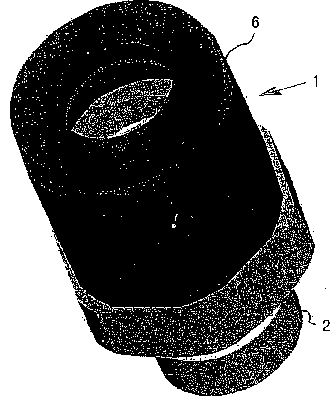
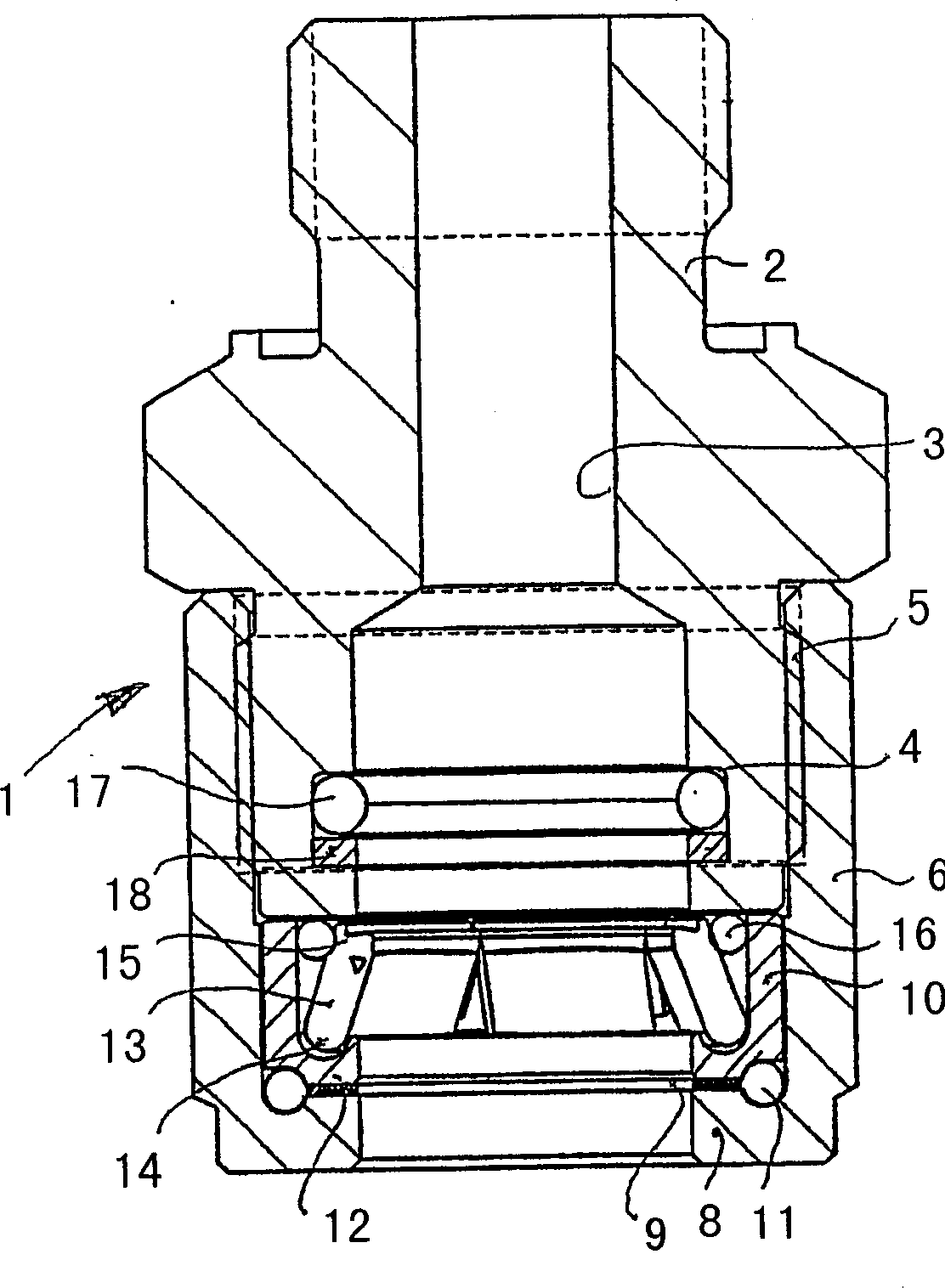
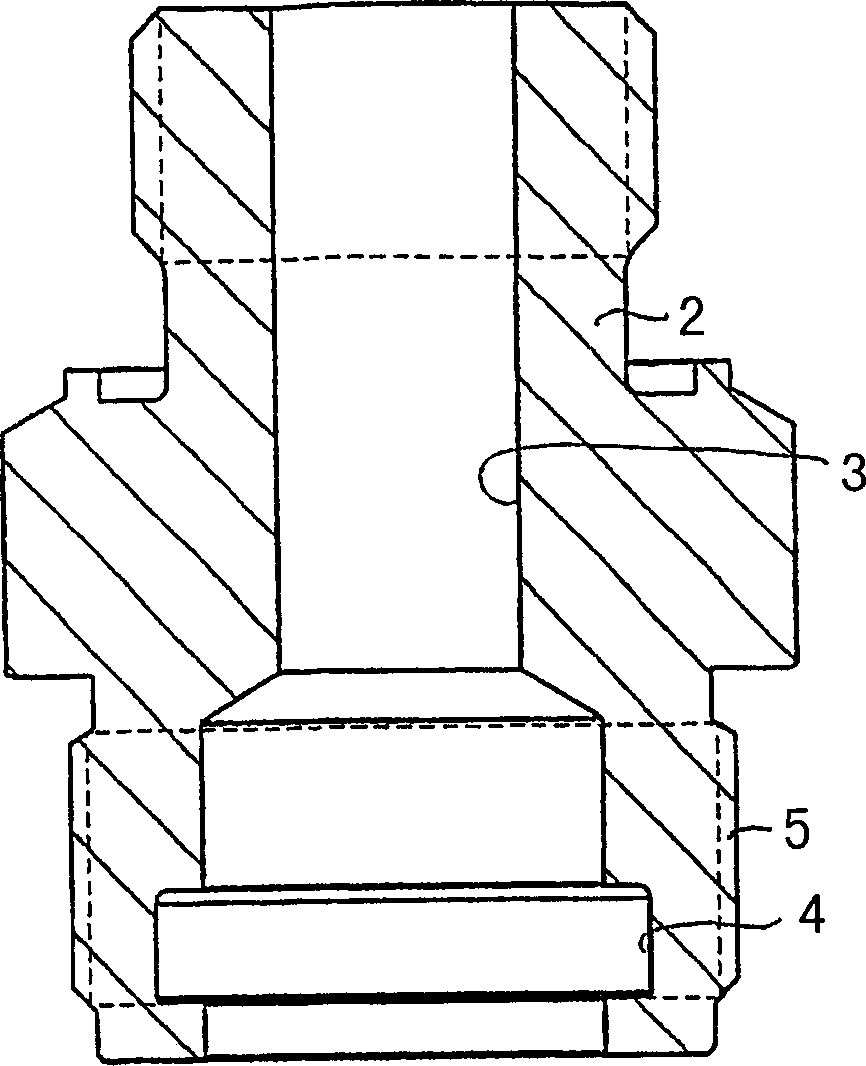
[0031] 1 denotes a female part comprising a rear, hose (not shown) receiving part 2 comprising a tubular lead-in part 3 to allow the passage of media such as hydraulic oil. At one end thereof, referred to here as the front end, the lead-in part 3 has a groove 4 thereon, which has a larger diameter than the lead-in part itself. The hose receiving part 2 has on its outside a threaded part 5 which is arranged to connect the hose receiving part 2 to a rotary part 6 .

[0032] The rotating part 6 consists of a substantially cylindrical tubular part having at its rear end an internal thread 7 arranged to cooperate with the thread 5 to connect the two elements 2 and 6 . The rotating part 6 has at its one end, here referred to as the front end, an annular flange 8 intended to be partly for a sliding seal 9 and partly for a substantially cylindrical tubular bearing supported thereon A support plane for the cup 10.

[0033] Between the rotating part 6 and the cylindrical tubular beari...


PUM


Abstract

The present invention relates to a quick joint coupling for liquid tight joining of lines under high pressure and comprising a sleeve shaped female part and a male part being introducible into the female part. A male part related to the female part comprises a cylindrical part being introducible into the female part of an envelope surface of which presents a first groove having a certain width. The first groove receives a ring being axially displaceable between the two walls of the groove, which the ring has substantially the same thickness as the depth of the first groove, and which the female part comprises a cylindrical space for receiving the cylindrical part of the male part. The envelope surface of the space is provided with at least a second groove for receiving elastically movable locking means out off and into the cylindrical part.

Description

technical field [0001] The invention relates to a quick connector for liquid-tight connection of high-pressure pipelines, which comprises a sleeve-shaped female part and a male part inserted into the female part, and a male part connected with the female part includes a Cylindrical part inserted into the female part, the envelope surface of which has a groove of specified width accommodating a ring movable axially between the two side walls of the groove, the ring having a The depth is substantially the same as the thickness, and the female part includes a cylindrical space for receiving the cylindrical part of the male part, the envelope of said space is provided with at least one groove for accommodating the exit or entry of the elastically movable locking means The cylindrical portion, the means cooperates in a locking position with the edge of the groove located closest to the outer end of the male part, and the locking means is displaceable by movement of the ring towards...

Claims


Application Information

Patent Timeline
Patent Type & Authority Applications(China)
IPC IPC(8): F16L27/08F16L37/12F16L37/53
CPCF16L37/12F16L27/08F16L37/53
Inventor W·奥尔松
Owner 斯进有限公司
Why Eureka
Try Eureka