Electrostatic cimple-beam interference light modulator

A light modulator and simply supported beam technology, applied in the field of spatial light modulation devices, can solve the problems of increasing the surface flatness of a movable mirror, low GLV effective area, and difficulty in integrating into an area array, etc., so as to improve the optical effective utilization area. , the effect of fast modulation speed and simple structure

Inactive Publication Date: 2006-05-24
CHONGQING UNIV
View PDF0 Cites 16 Cited by
  • Summary
  • Abstract
  • Description
  • Claims
  • Application Information

AI Technical Summary

Problems solved by technology

[0005] In order to overcome the shortcomings of complex DMD technology and the low effective area of ​​GLV, which is difficult to integrate into an area array, the purpose of the present invention is to provide an electrostatic simply supported beam interferometric light modulator. The simply supported beam adopts a wing-like shape, which can Reduce terrain effects and increase surface flatness of movable mirrors

Method used


Image

  • Electrostatic cimple-beam interference light modulator
  • Electrostatic cimple-beam interference light modulator
  • Electrostatic cimple-beam interference light modulator

Examples


Embodiment Construction

[0028] The present invention will be further described below in conjunction with accompanying drawing and specific embodiment:

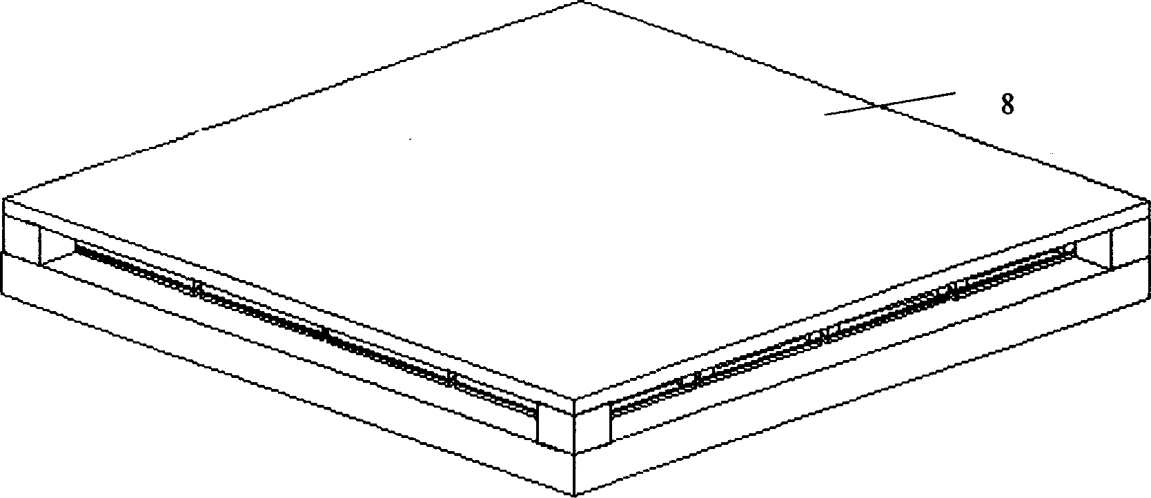
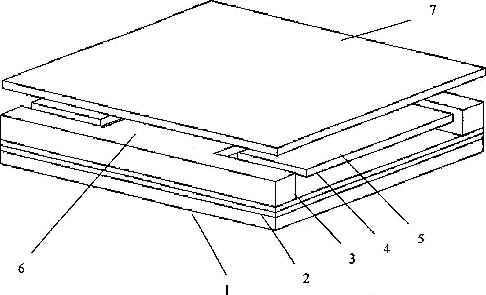
[0029] see figure 1 , image 3 and Figure 4 , the manufacturing process of this modulator is as follows: manufacture the control circuit on the substrate 1, sputter metal on it and form the lower electrode layer 2 by photolithography, the lower electrode layer 2 is in contact with the control end of each unit electrode of the control circuit, deposit a certain Thick insulating layer 3, sputtering metal aluminum to form wing-like simply supported beam 5 and support anchor 6, and then deposited on the support anchor to form a movable mirror 7, and finally the lower surface is coated with a semi-transparent film fixed A glass plate 8 (also called a fixed reflector) is covered above the movable reflector 7 by bonding, the four corners of the fixed glass plate 8 are supported on the substrate 1, and the lower surface of the fixed glass plate 8 is conne...


PUM


Abstract

The modulator is composed of substrate, control circuit, low electrodes layer, simply supported beam, movable reflector and fixed glass plate. Being formed on the substrate, low electrodes layer is contacted to control ends of each electrode in control circuit. The simply supported beam and support anchor are formed on the insulating layer, which is deposited on the low electrodes layer. Array of movable reflector is supported by the support anchor. The said array and the low electrodes layer constitutes parallel plate condenser with variable gap. There is certain gap between the fixed glass plate and the movable reflector. Shape of aircraft wing is adopted in the beam in order to reduce topographic effect and increase flatness of surface of movable reflector. Vertical up/down motion of the movable reflector happens under action of electrostatic force. Thus, the modulator modulates phase of light to realize switching state. Features are: quick response and simple structure.

Description

technical field [0001] The present invention relates to a spatial light modulation device. More specifically, the present invention is to change the distance between the glass plate and the movable reflector through electrostatic drive, so that the path difference changes when the incident light passes through, and utilizes the interference principle of light An electrostatic interference light modulator that modulates incident light. Background technique [0002] The prior art has disclosed a variety of optical modulators based on MEMS technology that can be used alone or together with other modulators, and these modulators include digital micromirror devices (DMDs) and grating light valves (GLVs). [0003] DMD is a modulator composed of millions of deflectable reflective micromirrors manufactured by MEMS technology. The total light extraction efficiency of the DMD imaging device is greatly improved, the modulation speed is fast, and the contr...

Claims


Application Information

Patent Timeline
Patent Type & Authority Applications(China)
IPC IPC(8): G02B26/06
Inventor 黄尚廉张洁张智海韩磊闫许伍艺
Owner CHONGQING UNIV
Why Eureka
Try Eureka