Facial mounting machine

A technology for surface mounting machines and assembly blocks, applied in electrical components, electrical components, etc., can solve problems such as increasing the number of parts and equipment large-scale, to improve impact absorption, prevent component adsorption position deviation, and improve adsorption stability. Effect

Active Publication Date: 2006-05-24
YAMAHA MOTOR CO LTD
View PDF2 Cites 23 Cited by
  • Summary
  • Abstract
  • Description
  • Claims
  • Application Information

AI Technical Summary

Problems solved by technology

However, there is also the following problem: In addition to the mechanism for adjusting the loading pressure by controlling the up and down movement of the single-axis table by the controller, it is necessary to separately install a tens

Method used


Image

  • Facial mounting machine
  • Facial mounting machine
  • Facial mounting machine

Examples


Embodiment Construction

[0038] Preferred embodiments of the present invention will be described below with reference to the drawings.

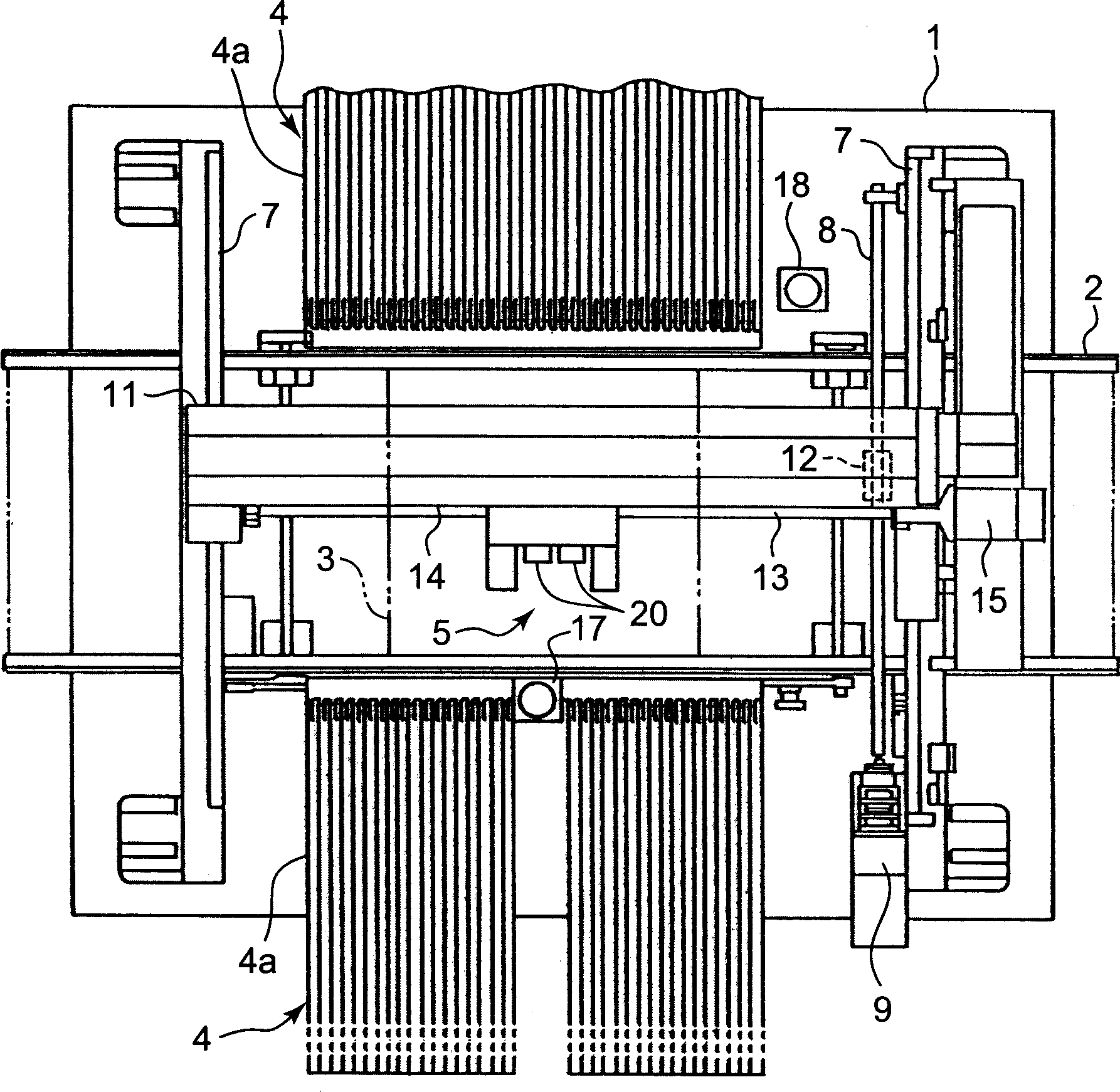
[0039] figure 1 The overall structure of the surface mounter according to the embodiment of the present invention is schematically shown. In this figure, a conveyor belt 2 constituting a conveyor line is provided on a base 1, and a printed circuit board 3 is conveyed on the conveyor belt 2 and stopped at a predetermined work position.

[0040] A component supply unit 4 is provided on the side of the conveyor belt 2 . Multiple rows of tape feeders 4 a are provided on this component supply unit 4 . Each tape feeder 4a draws out from a reel a paper tape containing and holding small electronic components such as ICs, transistors, and capacitors at predetermined intervals, and intermittently takes out the electronic components by the head unit 5 described later.

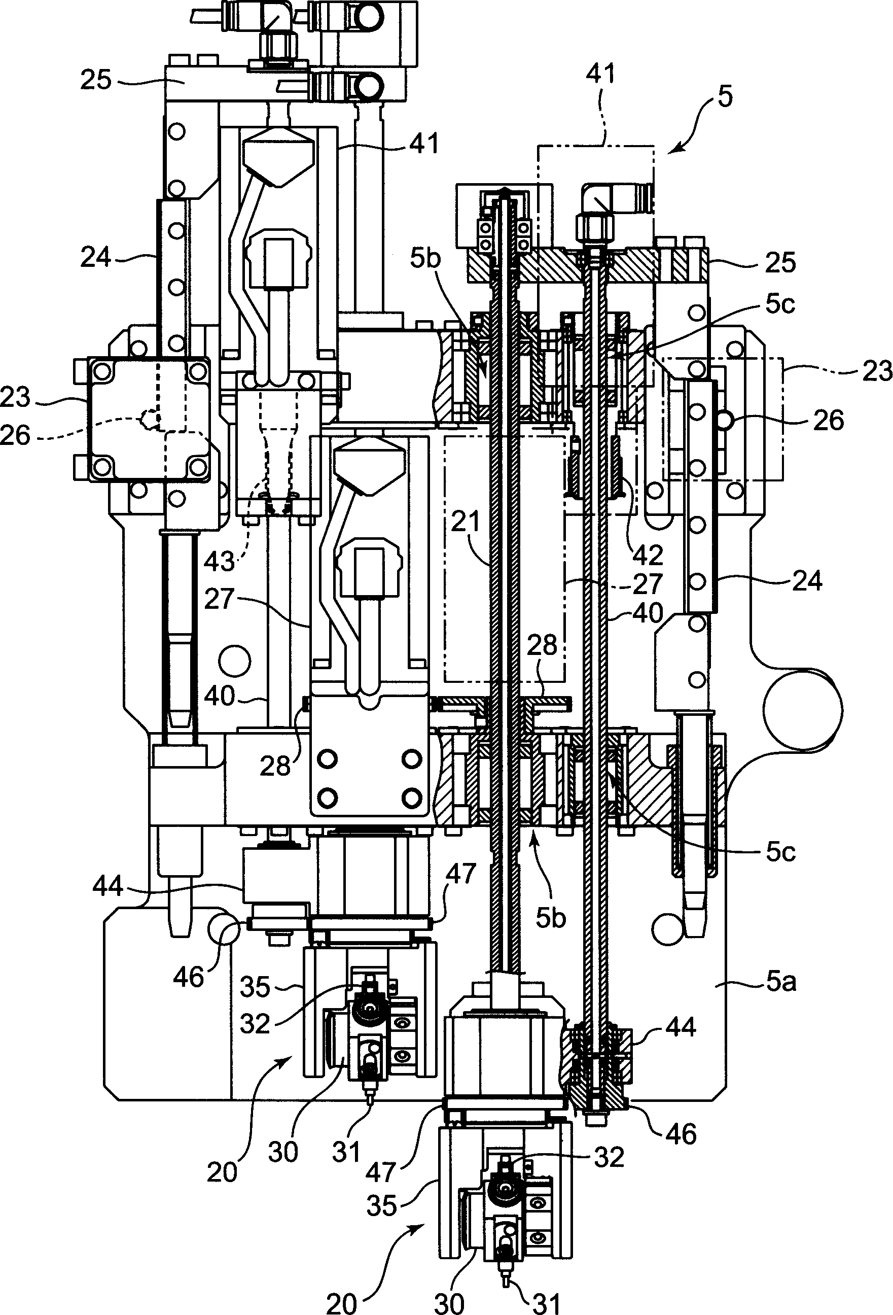
[0041] In addition, a head unit 5 for loading electronic components is provided above the above-mentioned ...


PUM


Abstract

The surface mounting machine of the present invention can set the load applied to the component below the weight of the movable part when the cushioning effect is exerted on the position of the lower end of the head when the component is sucked and mounted, and the load can be adjusted effectively. And the structure for adjusting the load can be easily maintained. The surface mounting machine includes a suction nozzle (31) and a component holding the suction nozzle, which is installed on the suction nozzle shaft (21), and a movable part that can relatively move a predetermined amount relative to the suction nozzle shaft in the up and down direction ; arranged between the above-mentioned nozzle shaft (21) and the above-mentioned movable part, a pressure chamber (70) for adjusting the pressing force applied to the above-mentioned movable part; and for providing pressure to the above-mentioned pressure chamber (70) The pressure supply device (80); the pressure supply device (80) can adjust the pressure provided to the above-mentioned pressure chamber (70) within the range from positive pressure to negative pressure.

Description

technical field [0001] The present invention relates to a surface mounter that absorbs components onto a component suction nozzle provided on a head unit and mounts them on a circuit board, and particularly relates to a device that can reduce the impact load of the suction nozzle when absorbing and mounting components surface mount machine. Background technique [0002] As we all know, most of the surface mounting machines used in the past adopt the following structure: the head unit is set to be movable on the XY plane, and the head unit is loaded with a suction nozzle shaft and a suction nozzle at the lower end. The mounting head is used to make it liftable. The mounting head of the head unit is used to absorb chip components such as ICs from the component supply part under negative pressure, and then transfer them to the printed circuit board and mount them on the printed circuit board. on the specified position on the circuit board. [0003] In this type of surface mou...

Claims


Application Information

Patent Timeline
IPC IPC(8): H05K13/04
Inventor 内山真浩
Owner YAMAHA MOTOR CO LTD
Why Eureka
Try Eureka