Elevator storey door unlocking device

A technology of unlocking device and locking device, which is applied to elevators, transportation and packaging in buildings, etc., can solve the problems of difficult-to-lock device operation and control, and reduced design.

Inactive Publication Date: 2006-05-24
MITSUBISHI ELECTRIC CORP
View PDF1 Cites 12 Cited by
  • Summary
  • Abstract
  • Description
  • Claims
  • Application Information

AI Technical Summary

Problems solved by technology

[0003] However, in such a conventional emergency unlocking device, since a keyhole for inserting an unlocking operation tool must be provided in the landing door or between the landing door and the door casing, the design property is reduced.
[0004] In addition, since the locking device is manually operated, it is difficult to associate the state of the locking device with the operation control of the car.

Method used


Image

  • Elevator storey door unlocking device
  • Elevator storey door unlocking device
  • Elevator storey door unlocking device

Examples


Embodiment Construction

[0013] Next, preferred embodiments of the present invention will be described with reference to the drawings.

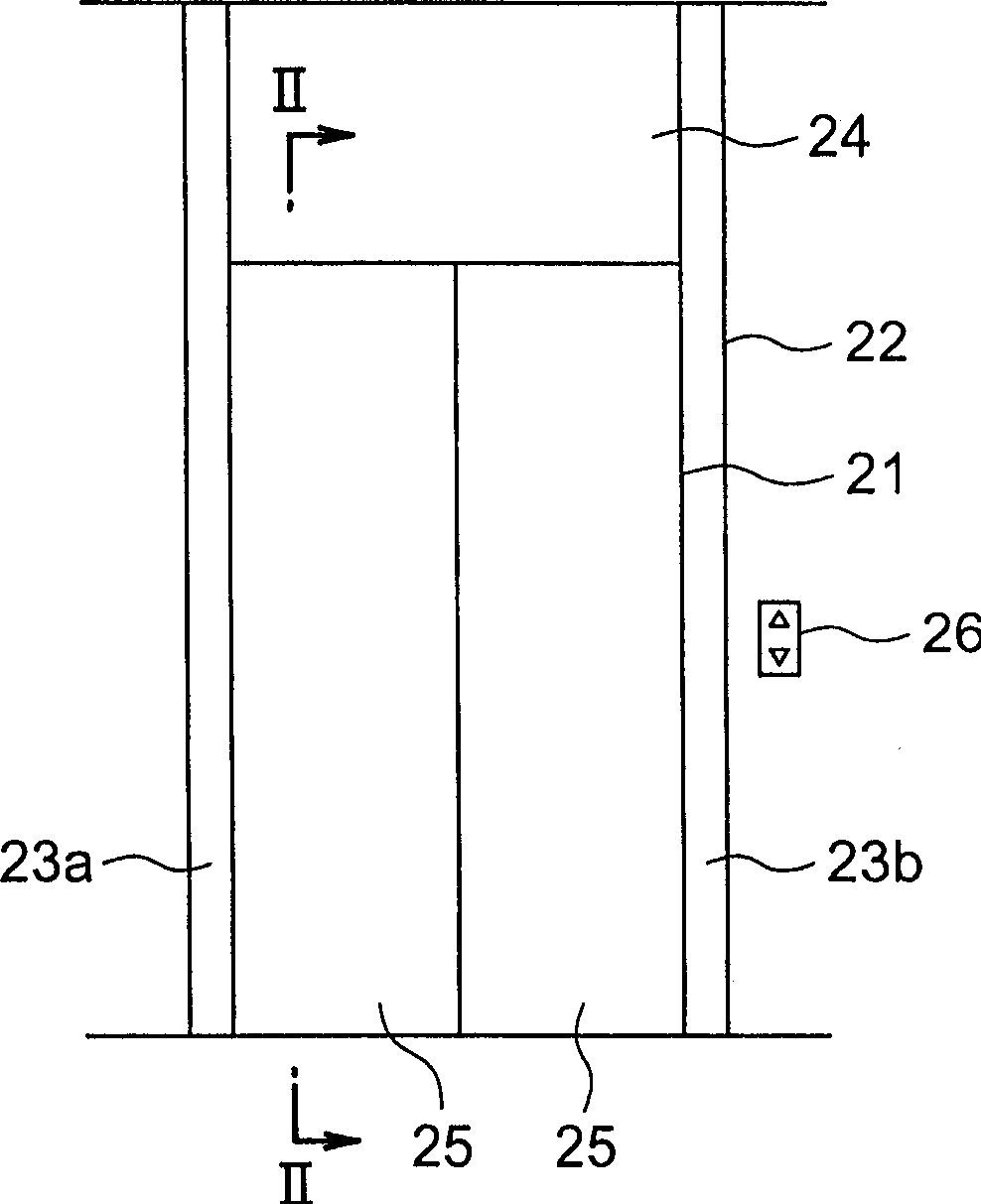
[0014] figure 1 It is a front view showing a hall of an elevator apparatus according to an example of an embodiment of the present invention. In the figure, the landing entrance 21 is provided in the landing. Door pockets 22 are fixed on both sides and the top of the landing entrance and exit 21 . The door casing 22 has a pair of vertical frames 23a, 23b and a door lintel board 24 .

[0015] The landing entrance 21 is opened and closed by a pair of landing doors 25 . A hall button device 26 is provided on the hall wall at the side of the hall entrance 21 .

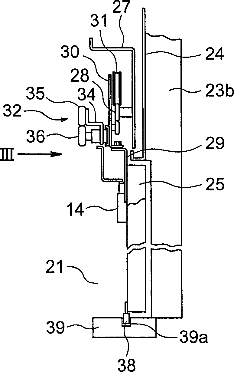
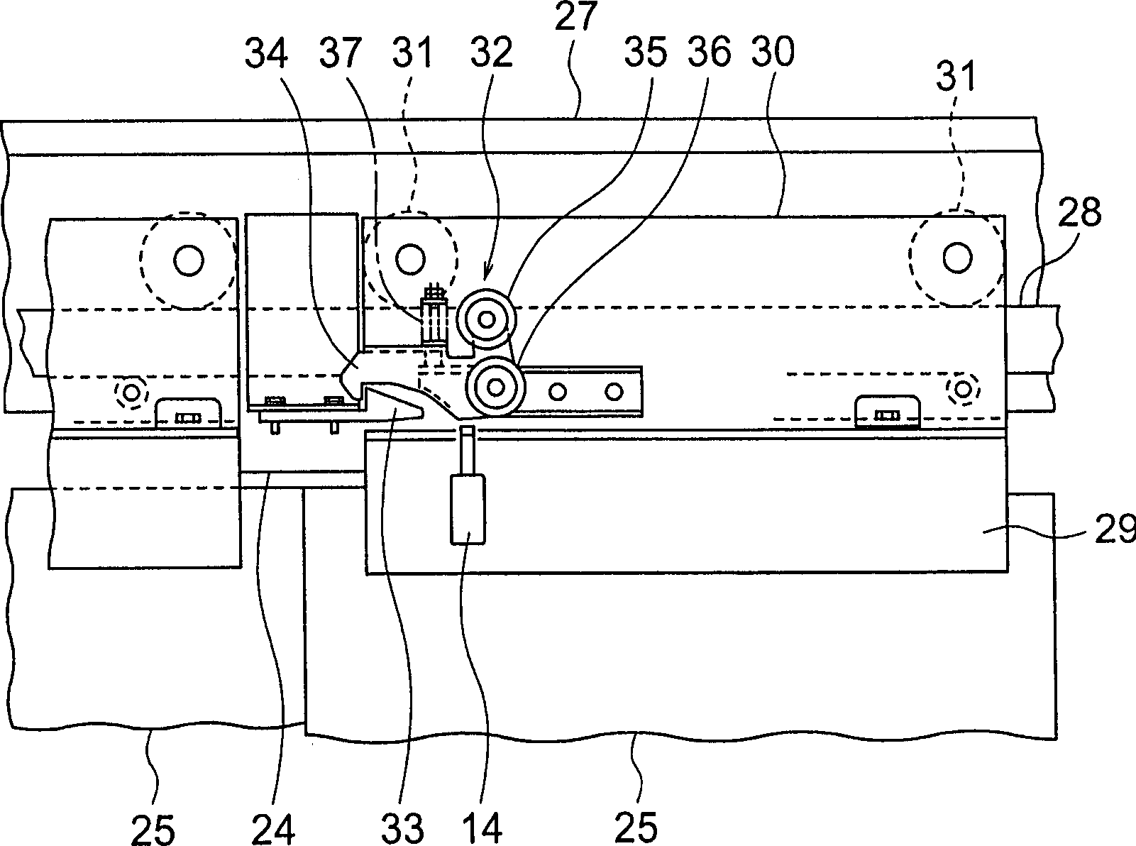
[0016] figure 2 is along figure 1 A cross-sectional view of the line II-II, image 3 yes means figure 1 Rear view of the main part of the landing. in addition, image 3 is along figure 2 The figure seen in the direction of arrow III. A hanger case (hanger case) 27 is fixed to an upper portion of the...


PUM


Abstract

The invention relates to a platform door unlocking device of an elevator, wherein the locking device of a platform door is operated by the driving of an actuator for unlocking. The actuator is controlled by an unlocking control part. The unlocking control part receives an unlocking instruction signal to make the actuator perform the unlocking operation.

Description

technical field [0001] The invention relates to an elevator landing door unlocking device for unlocking a landing door locking device. Background technique [0002] For example, Japanese Patent Laid-Open No. 3-152085 discloses a conventional emergency unlocking device that manually unlocks a locking device of a landing door by inserting an unlocking operation tool from the landing side. [0003] However, in such a conventional emergency unlocking device, since it is necessary to provide a keyhole for inserting an unlocking operation tool in the landing door or between the landing door and the door pocket, designability is reduced. [0004] In addition, since the locking device is manually operated, it is difficult to associate the state of the locking device with the operation control of the car. Contents of the invention [0005] The present invention was made to solve the above problems, and an object of the present invention is to provide an elevator landing door unloc...

Claims


Application Information

Patent Timeline
Patent Type & Authority Applications(China)
IPC IPC(8): B66B13/16
CPCB66B13/165
Inventor 久保田猛彦
Owner MITSUBISHI ELECTRIC CORP
Why Eureka
Try Eureka