Dust collector for vacuum cleaner

A technology for dust collectors and vacuum cleaners, applied in suction filters and other directions, can solve the problems of filter damage, deterioration of suction performance, deterioration of air flow, etc., to prevent the reduction of suction force, improve suction performance, and facilitate maintenance.

Inactive Publication Date: 2006-05-31
SANYO ELECTRIC CO LTD
View PDF0 Cites 3 Cited by
  • Summary
  • Abstract
  • Description
  • Claims
  • Application Information

AI Technical Summary

Problems solved by technology

At this time, the amount of dust that can be stored in the dust collection chamber decreases, and the suction force decreases in a relatively short period of time, so the suction performance deteriorates.
[0012] In addition, there is a vent (and a filter) extending in a direction intersecting with the flow direction of air and dust in the guide pipe, so dust is easily attached to the filter, and garbage with a high specific gravity (such as metal pieces) flows into the guide pipe. etc.), you will worry that the garbage will collide with the filter and cause the filter to be damaged
When dust adheres to the filter, the flow of air to the bypass flow path deteriorates and the suction force decreases
In addition, when the filter is damaged, there is a fear that garbage will flow into the bypass flow path and block it.
Therefore, in any case, there is a concern that the inhalation performance will deteriorate

Method used


Image

  • Dust collector for vacuum cleaner
  • Dust collector for vacuum cleaner
  • Dust collector for vacuum cleaner

Examples


Embodiment Construction

[0065] Hereinafter, embodiments of the present invention will be specifically described with reference to the drawings.

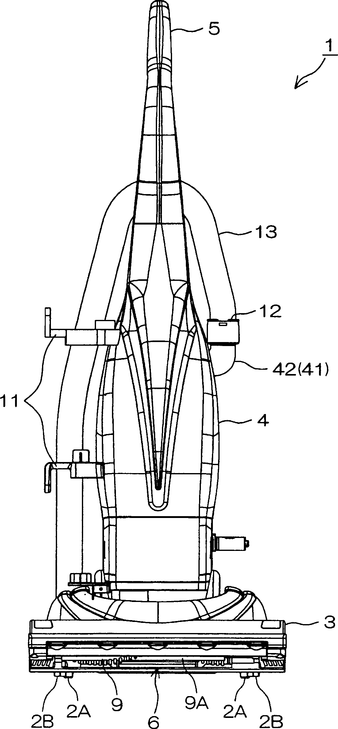
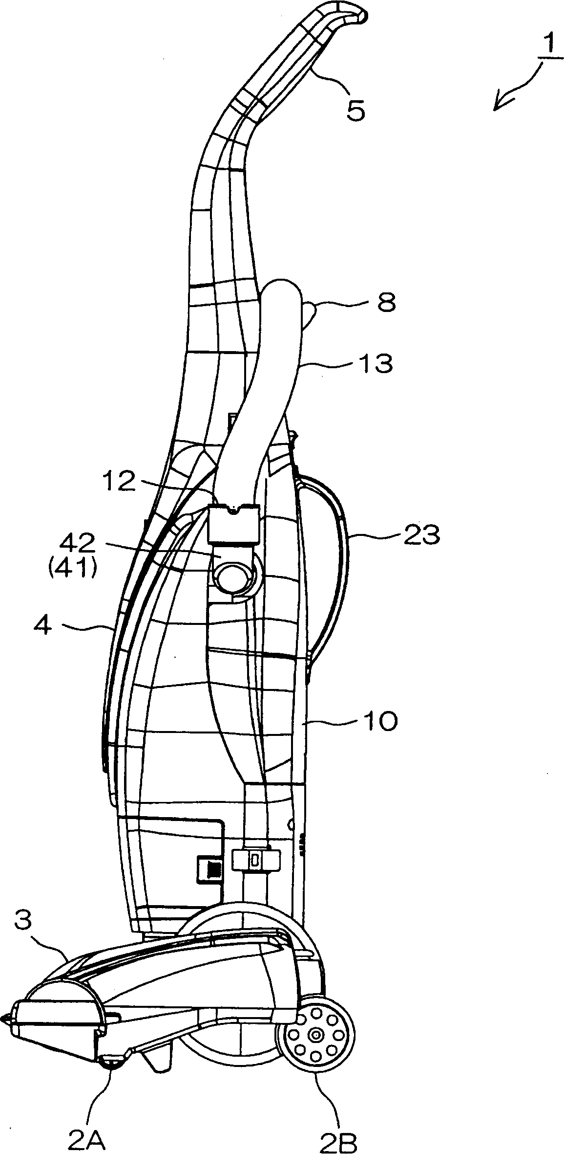
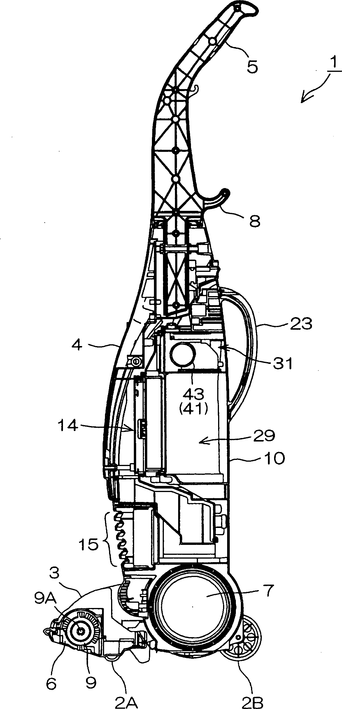
[0066] figure 1 It is a front view of the electric vacuum cleaner 1 which concerns on 1st Embodiment of this invention. figure 2 It is a left side view of this electric vacuum cleaner 1. image 3 It is a cross-sectional view of the electric vacuum cleaner 1 taken along a vertical plane in the front-rear direction as viewed from the left side.

[0067] refer to Figure 1 ~ Figure 3 The electric vacuum cleaner 1 is a so-called upright (vertical) vacuum cleaner, which is provided with a suction part 3 that moves along the ground, and a long strip-shaped main body 4 that is rotatably mounted on the suction part 3 at one end (lower end). It can be used in a posture of holding the handle 5 formed at the other end (upper end) of the main body 4 and tilting the main body 4 rearward at a predetermined angle (for example, 60° to 80°) with respect to the vertical...


PUM


Abstract

A dust collector for a vacuum cleaner capable of improving suction performance. The air and dust inhaled from the inlet (12) are guided to the dust collection chamber (29) through the guide path (41). A cylindrical flow path member (55) is arranged on the straight portion (52) of the guide pipe (41) such that its axis is along the direction in which the straight portion (52) extends. A plurality of vents (47) are formed on the flow path member (55), and each vent (47) is covered with a mesh filter (50). When a certain degree of dust is stored in the dust collection chamber (29), the air flowing in the introduction pipe (43) flows out to the outside (bypassing the flow path (31) side) through the vent (47) and bypasses the dust collection chamber (29) ) leads to the exit.

Description

technical field [0001] The invention relates to a dust collecting device for a vacuum cleaner which is suitable for an electric vacuum cleaner and is used to capture the dust sucked together with the air. Background technique [0002] There is known an electric vacuum cleaner provided with a dust collecting device detachable from the main body of the electric vacuum cleaner, and by collecting the air and dust sucked in from the suction part into the dust collecting device, the dust sucked together with the air can be captured in the dust collecting device. Inside the device, the air is exhausted from the main body through the dust collecting device. The air sucked into the dust collection device is guided to the dust collection chamber through the guide pipe, and then discharged through the filter. The dust sucked into the dust collecting device together with the air is captured by the filter when the air passes through the filter and stored in the dust collecting chamber. ...

Claims


Application Information

Patent Timeline
Patent Type & Authority Applications(China)
IPC IPC(8): A47L9/10
Inventor 吉田润高井启丰冈贤次
Owner SANYO ELECTRIC CO LTD
Why Eureka
Try Eureka