Cervical dilation monitor

A technology of cervix and uterus, applied in the field of cervical dilation monitor, which can solve the problems of expensive, non-disposable system, and insertion into patients

Inactive Publication Date: 2006-05-31
米基·巴恩-克纳安 +2
View PDF4 Cites 5 Cited by
  • Summary
  • Abstract
  • Description
  • Claims
  • Application Information

AI Technical Summary

Problems solved by technology

However, both systems are non-disposable, expensive and inserted into the patient

Method used


Image

  • Cervical dilation monitor
  • Cervical dilation monitor
  • Cervical dilation monitor

Examples


Embodiment Construction

[0052] The present invention resides in the construction of a cervical dilation monitor and its method of operation.

[0053] The principles and operation of a cervical dilation monitor according to the present invention may be better understood with reference to the drawings and accompanying description.

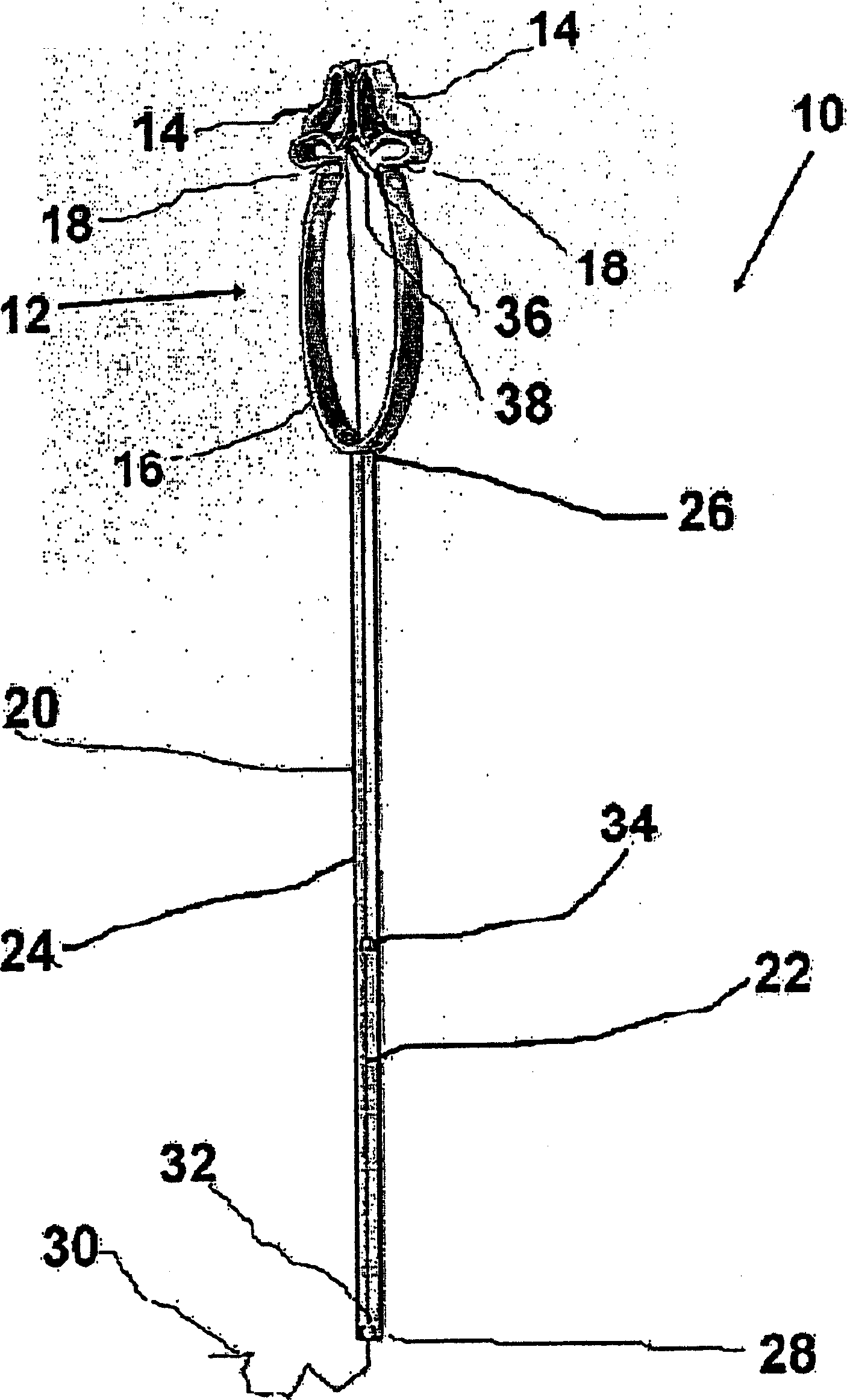
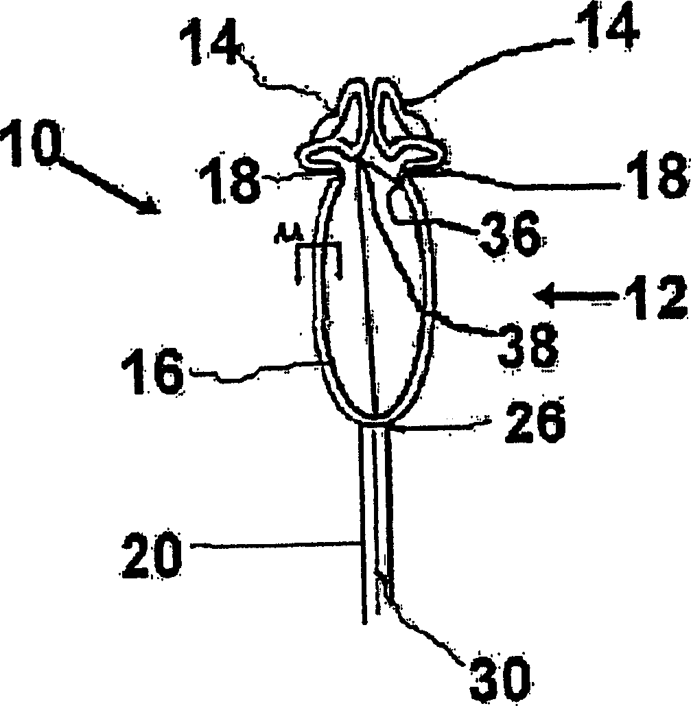
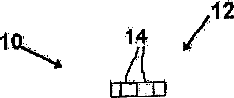
[0054] now refer to Figure 1 to Figure 5 . figure 1 is a perspective view of a cervical dilation monitor 10 constructed and operative in accordance with a preferred embodiment of the present invention. figure 2 is a front view of the cervical dilation monitor 10 . image 3 is a top view of the cervical dilation monitor 10. Figure 4 is a front view of the cervical dilation monitor 10 fully expanded. Figure 5 is a top view of the cervical dilation monitor 10 fully expanded. Cervical dilation monitor 10 includes an expandable grasping device 12 having two oppositely facing grasping members 14 and an outwardly biased reset member 16 . The expandable grasping device 12 is...


PUM


Abstract

A system for measuring cervical dilation of a woman's uterus during a first stage of labor comprising an expandable grasping device having two oppositely facing grasping members configured such that The grasping device grasps the dilated cervix. The system also includes a first elongated element having a calibration scale disposed thereon, and a second elongated element. The second elongated portion has an indicator disposed thereon. The first and second elongated elements are mechanically connected to the grasping device in such a way that when the grasping device is expanded with a dilated cervix, the first and second elongated elements Relative linear motion is created between the second elongate members, thereby moving the indicator relative to the calibrated scale to give a measure of cervical dilation.

Description

technical field [0001] The invention relates to a medical device, in particular to a cervical dilation monitor. Background technique [0002] As an introduction, it remains standard practice among obstetricians to assess the progress of labor during the first stages of active labor by performing a routine vaginal examination to estimate cervical dilation. At this stage of labor, the cervix dilates to about 10 cm and effaces into a very thin layer. However, these examinations are uncomfortable for the patient, imprecise, objective and risk introducing infectious diseases into the uterus, disadvantages that are amplified if consecutive examinations are performed by different observers. [0003] Related to the present invention is US Patent No. 5,658,295 to Krementsov, which relates to a caliper-like instrument having graduations for indicating dilation. The device to which Krementsov relates was not designed to remain in place for continuous monitoring. In addition, the dev...

Claims


Application Information

Patent Timeline
Patent Type & Authority Applications(China)
IPC IPC(8): A61B5/103A61B5/107A61B5/117
CPCA61B5/1076A61B5/435A61B1/303
Inventor 米基·巴恩-克纳安伊兰·哈勒维巴拉克·哈勒维
Owner 米基·巴恩-克纳安
Why Eureka
Try Eureka