
Push-stop bar unit

A technology of stop rods and struts, which is applied in the field of shock stop rods, and can solve problems such as permanent deformation of shock stop rods

Active Publication Date: 2006-06-07
HUSQVARNA AB
View PDF1 Cites 0 Cited by
  • Summary
  • Abstract
  • Description
  • Claims
  • Application Information

AI Technical Summary

Problems solved by technology

Frequent occurrences of clumsy use often lead to permanent deformation of the impact stop lever, which in turn leads to costly downtime

Method used


Image

  • Push-stop bar unit
  • Push-stop bar unit
  • Push-stop bar unit

Examples


Embodiment Construction

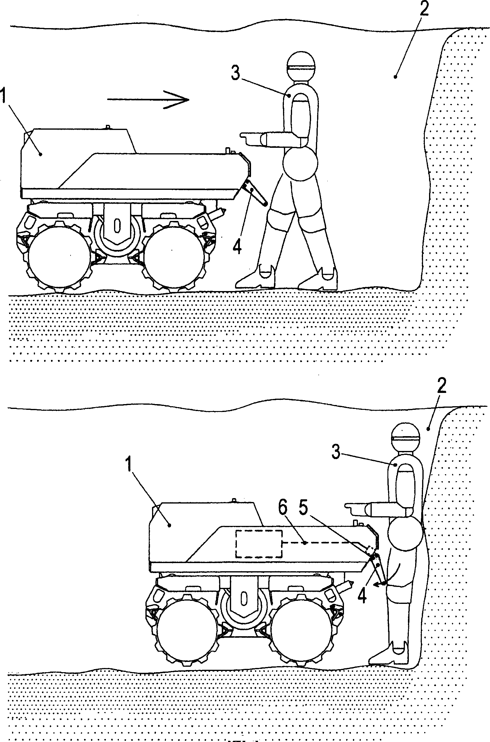
[0007] figure 1 A self-propelled walk-controlled roller compactor is shown in the form of a trench compactor 1 in operation. The trench compactor 1 has vibrating drums fitted with pads and is used to compact the bottom of the trench 2 . The trench compactor 1 is usually remotely controlled by an operator standing on the edge of the trench 2 . In the figure, because the operator 3 manually operates the trench compactor 1, he comes down into the trench 2.

[0008] In the upper part of the figure, the operator 3 has activated the trench compactor 1 to reverse in the direction of the arrow and is walking backwards behind the compactor. The trench compactor 1 is equipped with an impact stop bar 4 according to the invention. At this moment, the impact stop lever 4 is in an effective non-triggered state.

[0009] In the lower part of the figure, the backward movement of the operator 3 has been stopped by an obstacle, and he does not try to bring the trench compactor 1 in reverse ...


PUM


Abstract

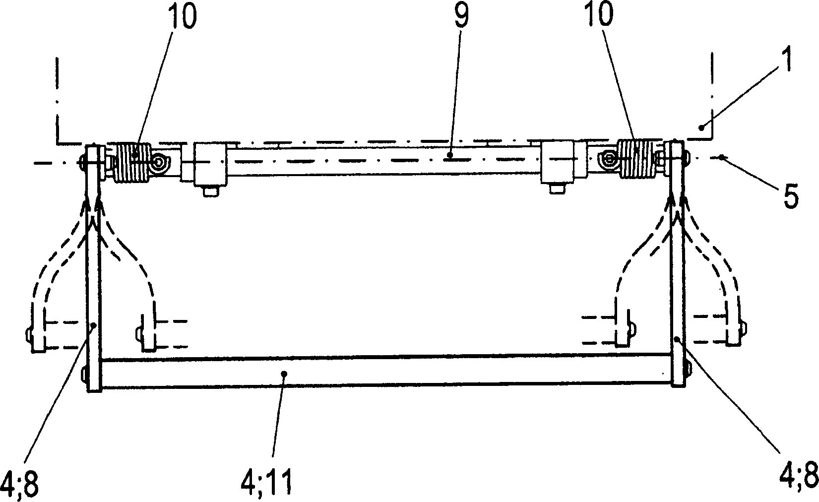
An impact stop bar (4) with a strut (8), which is mounted on an anti-collision device (6) for a self-propelled walking control roller (1), and communicates with the walker through the strut (8) The control roller (1) is pivotably connected. Strut (8) is made of plastics, rubber or composite material.

Description

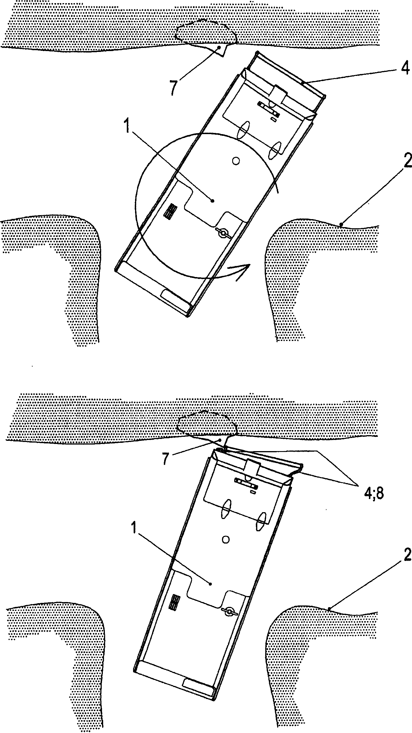
technical field [0001] The present invention relates to a push-stop bar mounted on an anti-collision device for a self-propelled walk-controlled roller compactor. The aim is to obtain an impact stop lever that is flexible when overloaded and thus more durable when used awkwardly. The impact stop bar is suitable for use with an anti-collision device for a heavy walk control roller, such as a trench compactor. Background technique [0002] Pedestrian control rollers can be operated with a joystick. When such a machine reverses, there is a risk that the operator does not notice the obstacle behind and that a collision occurs between the rod end and the obstacle. It is known that machines of this type can be equipped with an anti-collision device to protect the operator from injuries caused by collisions. The anti-collision device may also include replaceable impact stop plates and impact stop levers associated with the function of being able to stop the reverse operation of ...

Claims


Application Information

Patent Timeline
Patent Type & Authority Applications(China)
IPC IPC(8): E02D3/046B60T7/22E01CE01C19/26E02D3/032F16P3/00
CPCB60T7/22E01C19/262E02D3/032E01C19/283
Inventor G·佩尔松
Owner HUSQVARNA AB
Learn More