Luminous fabric device

A technology of light-emitting fabrics and optical fibers, applied in fabrics, display devices, textiles, etc., can solve problems such as inability to produce light, and achieve the effects of easy conversion, low power, and good service life

Inactive Publication Date: 2006-06-07
BAYCOM OPTO ELECTRONICS TECH
View PDF0 Cites 10 Cited by
  • Summary
  • Abstract
  • Description
  • Claims
  • Application Information

AI Technical Summary

Problems solved by technology

However, such active luminescent ornaments can only produce point-like or partial luminous effects, and cannot produce large-area luminous

Method used


Image

  • Luminous fabric device
  • Luminous fabric device
  • Luminous fabric device

Examples


Embodiment Construction

[0035] In order to make the above and other purposes, features, advantages and specific embodiments of the present invention more obvious and understandable, the detailed description is as follows according to the accompanying drawings:

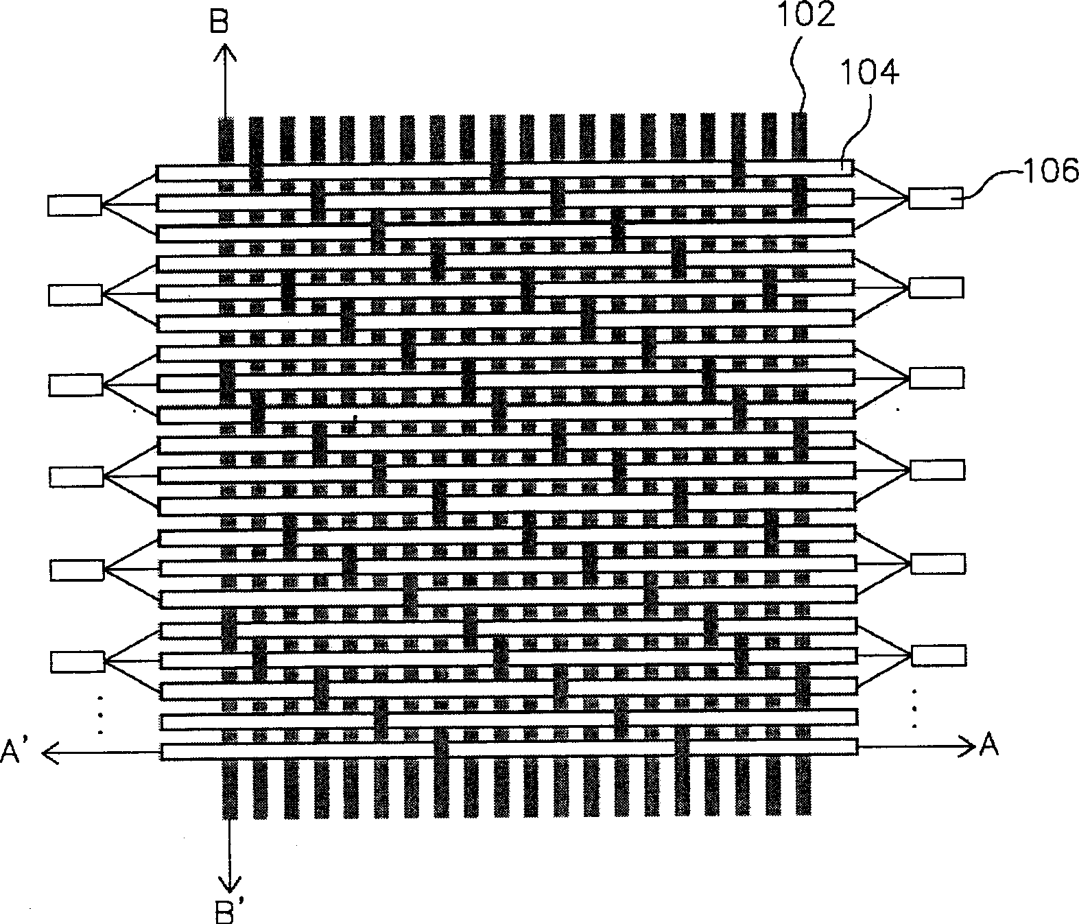
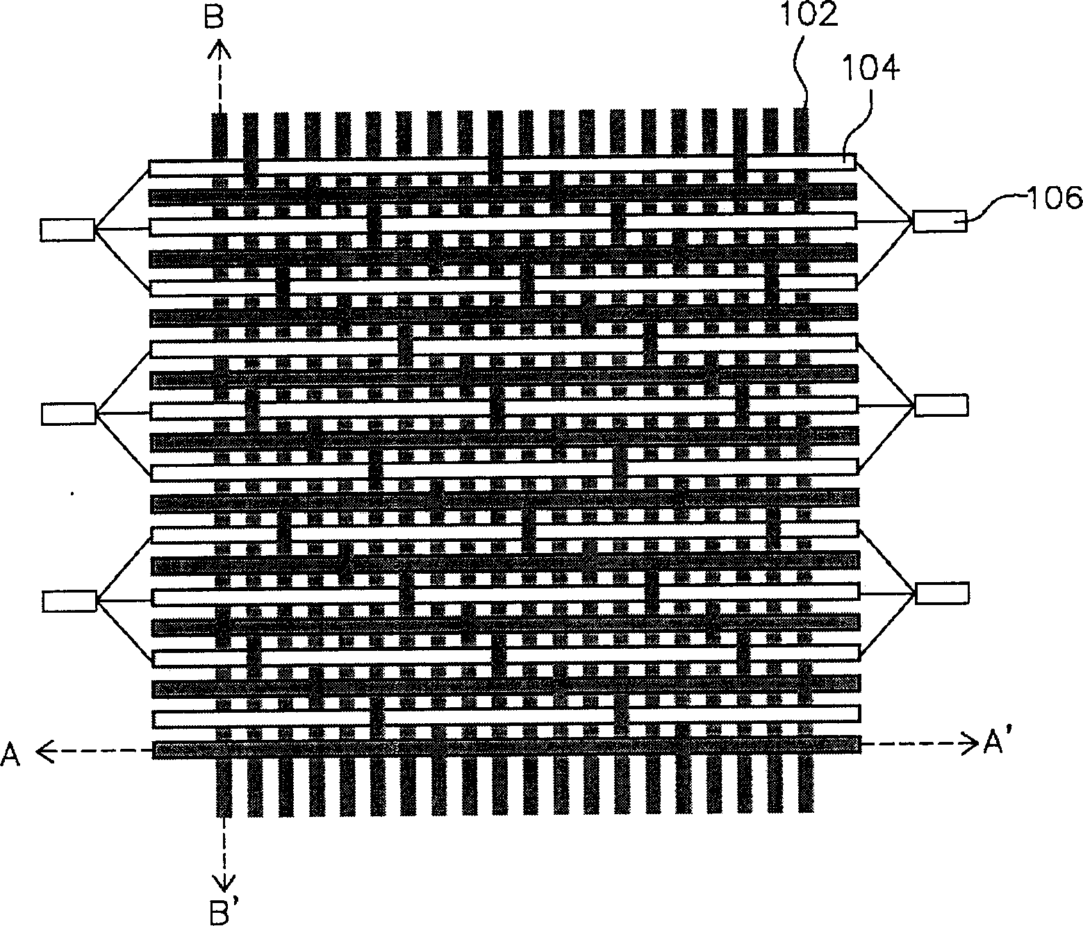
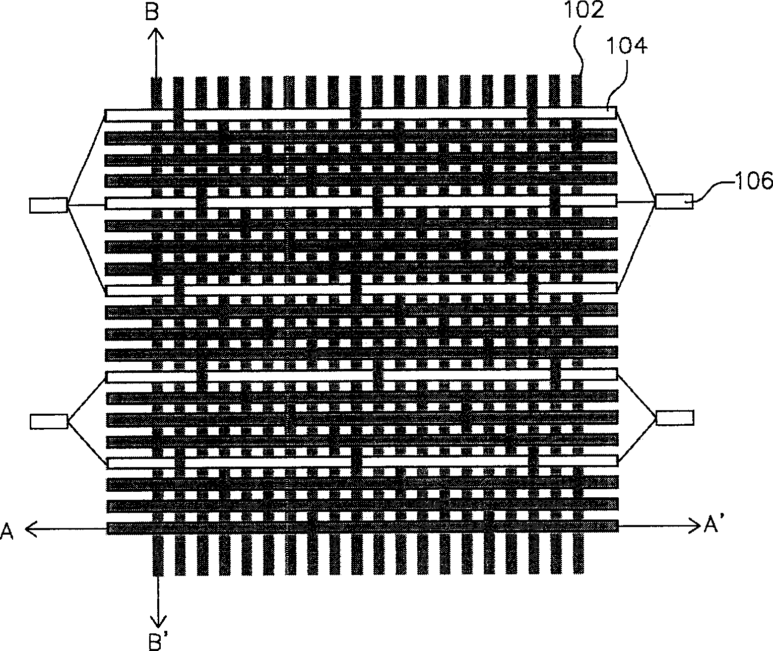
[0036] The invention provides an active light-emitting fabric device using an optical fiber cloth layer as a light source. According to the light-emitting fabric device of the present invention, compared with the traditional active light-emitting fabric device, it has the advantages of better service life, power saving, light and thin volume, and can be applied to clothing, such as warning vests, raincoats, or ornamental clothing, etc. . In addition, it can also be applied to entertainment products, such as toys, kites, dolls, etc.

[0037] According to the luminescent fabric device of the present invention, it includes a pattern layer and an optical fiber cloth layer. The pattern layer is composed of a light-transmitting area and a non-lig...


PUM


Abstract

The luminous fabric device includes one pattern layer and one optical fiber fabric layer. The pattern layer consists of one transparent area and one opaque area and forms the displayed pattern. The optical fiber fabric layer is woven with optical fibers and yarns and is used to provide light source for the luminous fabric device. The optical fiber fabric layer is fixed to the pattern layer through sewing or through one fixing assembly.

Description

technical field [0001] The present invention relates to a luminous textile device, more specifically, to a luminous textile device using an optical fiber cloth layer as a light source. Background technique [0002] General luminous ornaments can be roughly divided into two types. One is passive reflective ornaments coated with reflective materials, such as fluorescent paints, which appear through reflection. However, the luminous intensity produced by this passive reflective luminescent ornament is limited by the intensity of the irradiating light source. When the intensity of the irradiating light source is insufficient, the reflective effect it produces will also decrease, resulting in the failure to achieve the purpose of clear luminous display. . [0003] The other type is active light-emitting ornaments, which are usually equipped with a light source, such as a light-emitting diode, to achieve the effect of light-emitting display through the light generated by the ligh...

Claims


Application Information

Patent Timeline
Patent Type & Authority Applications(China)
IPC IPC(8): G09F13/00D03D15/20D03D15/547G09F23/00
Inventor 彭启宗刘胜德王清山
Owner BAYCOM OPTO ELECTRONICS TECH
Why Eureka
Try Eureka