
Axial air-gap electronic motor

一种轴向气隙、电动机的技术,应用在制造电动发电机、电动组件、带有静止电枢和旋转磁体的同步电动机等方向,能够解决不能位置检测、高精度的感测难以进行、制造成本提高等问题,达到可靠感测、高精度感测的效果

Active Publication Date: 2006-06-07
FUJITSU GENERAL LTD
View PDF3 Cites 11 Cited by
  • Summary
  • Abstract
  • Description
  • Claims
  • Application Information

AI Technical Summary

Problems solved by technology

[0007] In addition, in the method described in Patent Document 2, since a magnet and mounting parts dedicated to position detection are required, the manufacturing cost is relatively increased, and the weight of the rotor itself is correspondingly increased due to the increase of the detection magnet, and it will cause Increased power consumption
[0008] In addition, when the position detection sensor is attached to the back side of the rotor, a communication hole for obtaining a magnetic gap is provided in a part of the rotor rear yoke, but the communication hole is not only prone to positional deviation during the drilling process. , and the distance between the magnet and the position detection sensor becomes longer, and it becomes difficult to perform high-precision sensing accordingly
[0009] Furthermore, in the case where the position detection sensor is attached to the stator side as shown in Patent Document 3, the position detection sensor is easily affected by the magnetic field generated by the stator, and thus cannot perform accurate position detection.

Method used


Image

  • Axial air-gap electronic motor
  • Axial air-gap electronic motor
  • Axial air-gap electronic motor

Examples


Embodiment Construction

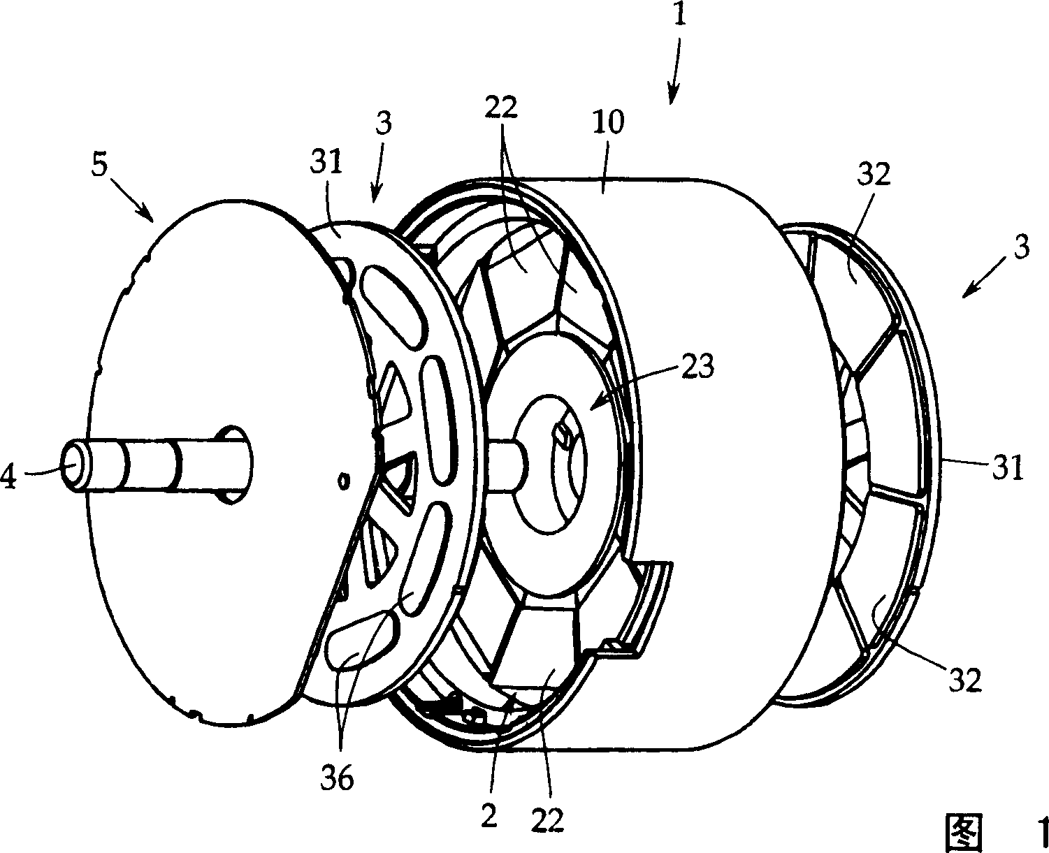
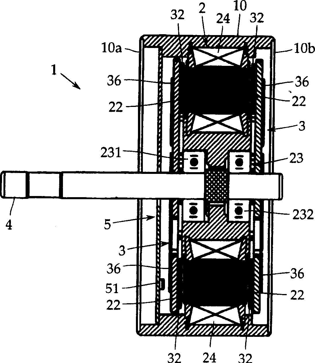
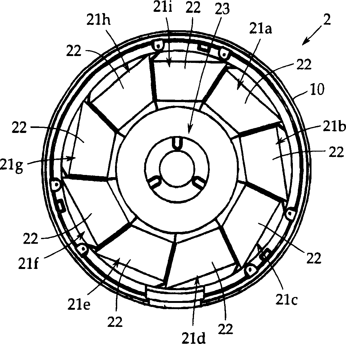
[0040] Next, embodiments of the present invention will be described with reference to the drawings. In addition, the present invention is not limited thereto. 1 is an exploded perspective view of an axial air gap motor according to a first embodiment of the present invention, figure 2 It is a central longitudinal sectional view of the first embodiment, image 3 It is a front view of a stator, and FIGS. 4A to 4C are a front view, a rear view, and an A-A line sectional view of a rotor according to the first embodiment.

[0041] This axial air-gap motor 1 includes a stator 2 formed in a disk shape, and a pair of rotors 3, 3 disposed on opposite sides of the stator 2 with a predetermined gap (gap). Each rotor 3, 3 is fixed coaxially to a rotor output shaft 4 that outputs a rotational drive force.

[0042] The stator 2 and the rotor 3 are accommodated in a cylindrical case 10 . In this example, at both ends of the housing 10, such as figure 2 As shown, disc-shaped cover member...


PUM


Abstract

It is an object of the present invention to provide an axial air-gap motor that can prevent magnets from falling off at low cost and that can perform reliable position detection. An axial air gap type motor, wherein the tooth surface of the stator and the magnet surface of the rotor are arranged opposite to each other along the axial direction of the output shaft of the rotor with a predetermined gap, wherein the rotor is equipped with: The arranged rotor back yoke, the rotor magnet attached to the above-mentioned rotor back yoke so as to face the tooth surface of the above-mentioned stator, and the above-mentioned rotor magnet has a Anchor magnets on the back side. On the back side of the rotor rear yoke (31) of the rotors (3, 3), an anchor magnet (36) integrated with the rotor magnet (32) via a through hole (35) is provided to fix the rotor magnet (32), Further position detection is performed with an anchor magnet (36).

Description

technical field [0001] The present invention relates to an axial air-gap motor in which the rotor and the stator are disposed opposite to each other along the axial direction of the rotor output shaft. Air-gap motors. Background technique [0002] An axial air gap motor is, for example, shown in Patent Document 1 (Japanese Patent Application Publication No. H03-212141), which is a motor in which a rotor is opposed to one or both sides of a stator with a predetermined gap. It is characterized in that it can be made thinner in the direction of the rotating shaft, that is, can be flattened, compared with a radial air gap motor such as an inner rotor type. [0003] In general, the rotor includes: a rotor rear yoke formed of a disc body, and a rotor magnet integrally attached to the surface of the rotor rear yoke facing the stator, and the rotor magnet is integrally attached by an adhesive or the like. to the rear yoke of the rotor. [0004] In addition, a brushless motor incl...

Claims


Application Information

Patent Timeline
Patent Type & Authority Applications(China)
IPC IPC(8): H02K1/27
CPCH02K21/24H02K1/2798H02K11/215H02K29/08H02K15/03H02K1/2793H02K1/182H02K2213/03H02K2201/03
Inventor 丹野俊昭小岛智则
Owner FUJITSU GENERAL LTD
Features
  • Generate Ideas
  • Intellectual Property
  • Life Sciences
  • Materials
  • Tech Scout
  • Unparalleled Data Quality
  • Higher Quality Content
  • 60% Fewer Hallucinations
Learn More