Ring fixing structure of motor bearing of washing machine

A technology for motor bearings and fixed structures, which is applied to electromechanical devices, shafts, bearings, shafts, etc., can solve the problems of insufficient strength, high tariff freight costs, etc., and achieve the effect of reducing the cost of motors

Inactive Publication Date: 2006-06-07
LG ELECTRONICS (TIANJIN) APPLIANCES CO LTD
View PDF0 Cites 10 Cited by
  • Summary
  • Abstract
  • Description
  • Claims
  • Application Information

AI Technical Summary

Problems solved by technology

[0007] However, the limit snap ring 4 of the above-mentioned structure is an imported product, and the tariff freight cost is relatively high, and then localization is implemented, but the strength of the domestic product cannot meet the required requirements of the product.

Method used


Image

  • Ring fixing structure of motor bearing of washing machine
  • Ring fixing structure of motor bearing of washing machine
  • Ring fixing structure of motor bearing of washing machine

Examples


Embodiment Construction

[0025] The ring fixing structure of the washing machine motor bearing of the present invention will be described in detail below with reference to the accompanying drawings and specific embodiments.

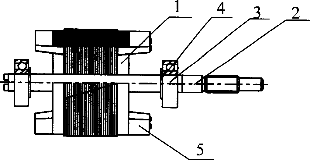
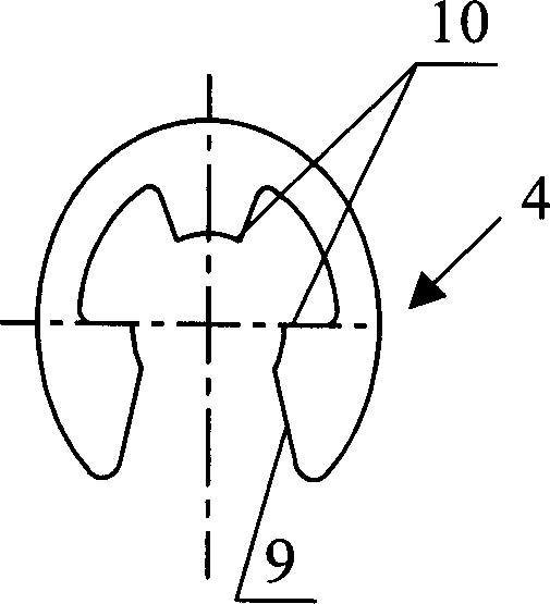
[0026] Figure 5 It is a structural schematic diagram of the connection between the motor rotor and the motor shaft and bearings of the present invention; Image 6 is a structural schematic diagram of the spacer ring of the present invention; Figure 7 yes Image 6 side view of Figure 8 It is a structural schematic diagram of the combination of the limiting ring and the motor shaft of the present invention.

[0027] As shown in the figure, the ring fixing structure of the washing machine motor bearing includes a motor shaft 6 fixed at the center of the motor rotor 1; a bearing 3 connected to the motor shaft 6, and the bearing 3 is a ball bearing; A limiting ring 7 for limiting; a limiting protrusion 8 is formed at the position where the motor shaft 6 is located at the bearin...


PUM


Abstract

This invention discloses a ring fixing structure for a washing machine motor bearing including a motor shaft fixed at the center of a motor rotor, a bearing connected with the shaft, a spacing ring for limiting the bearing, in which, limiting cams are formed at the bearing on the shaft for clamping the spacing ring, which is a round plane sheet one with the shaft passing through, more than two spacing humps are set on the shaft and the ring fixing structure is processed with a broach cutting on the original shaft to heave the edge of the shaft to clamp the spacing ring.

Description

technical field [0001] The invention relates to a washing machine motor. In particular, it relates to a ring fixing structure of a washing machine motor bearing with simple structure and low manufacturing cost. Background technique [0002] The motor consists of a rotor that is press-fitted to a rotating shaft, and a stator that keeps a certain distance from the rotor to rotate the rotor. [0003] The stator includes an iron core and coils. Wherein the stator core includes a plurality of protruding winding portions and slots formed between the winding portions. The coil is wound around the winding portion of the iron core. The shape and size of each winding part and groove are consistent. When power is applied to the coil of the stator, a magnetic flux will be formed in the gap between the stator and the rotor, and the distribution of the magnetic flux in the gap must be in the form of a sine wave, which is beneficial to the performance and noise of the motor requiremen...

Claims


Application Information

Patent Timeline
Patent Type & Authority Applications(China)
IPC IPC(8): H02K7/08F16C3/02
Inventor 刘志刚
Owner LG ELECTRONICS (TIANJIN) APPLIANCES CO LTD
Why Eureka
Try Eureka