

Multi-output power supply circuit
A power circuit and multi-output technology, which is applied in the direction of output power conversion devices, electrical components, DC power input conversion to DC power output, etc., can solve the problems of difficult miniaturization and large number of components
- Summary
- Abstract
- Description
- Claims
- Application Information
AI Technical Summary
Problems solved by technology
Method used
Image

Examples
no. 1 Embodiment approach 》
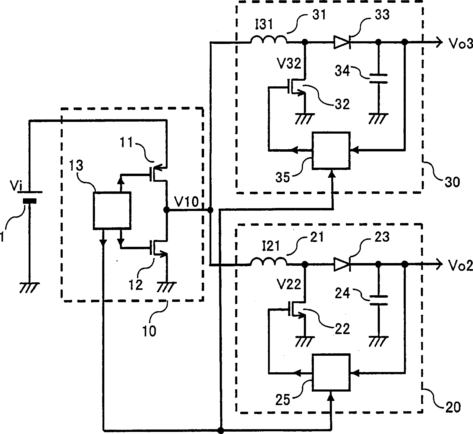
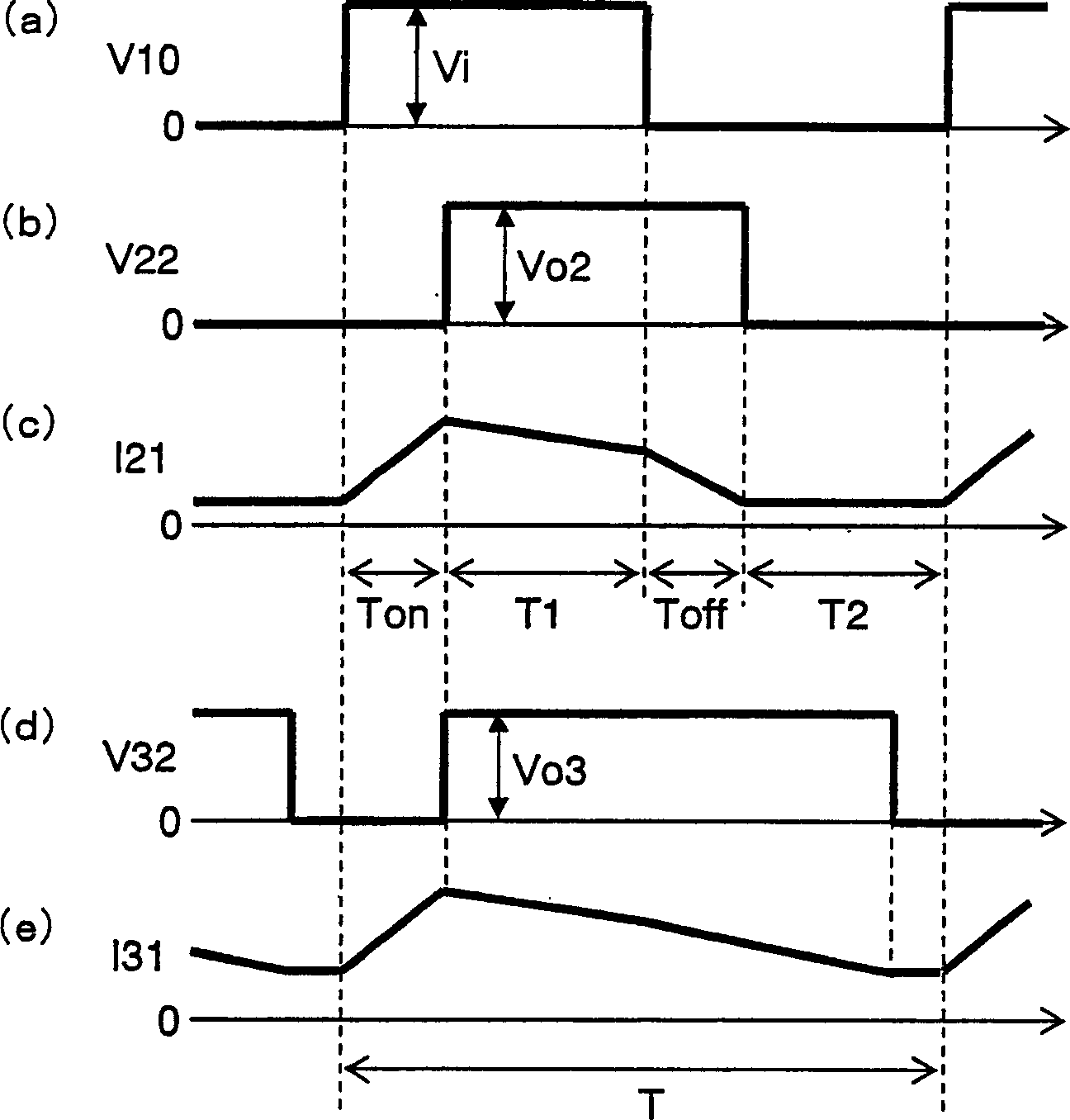
[0049] figure 1 It is a circuit diagram showing the configuration of the multi-output power supply circuit according to the first embodiment of the present invention.
[0050] like figure 1 As shown, the multi-output power supply circuit of the first embodiment is composed of a switch circuit 10 connected to an input DC power supply 1 that outputs an input DC voltage Vi, and booster circuits 20 and 30 that generate two outputs.
[0051] The switch circuit 10 is composed of a high switch 11 , a low switch 12 and a step-down control circuit 13 . The high switch 11 is composed of a P-channel FET, and its source is connected to the input DC power supply 1 . The low switch 12 is composed of an N-channel FET, its drain is connected to the drain of the high switch 11 , and its source is grounded. The step-down control circuit 13 applies a pulse voltage to each gate of the high switch 11 and the low switch 12, and controls the high switch 11 and the low switch 12 to be turned off...
no. 2 Embodiment approach 》
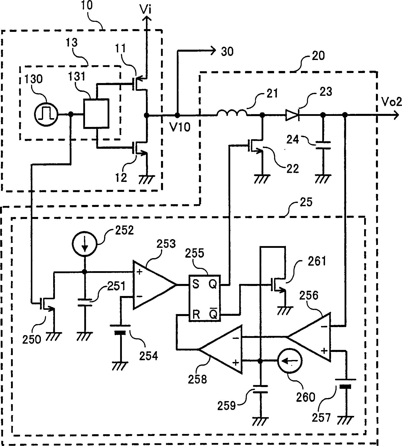
[0078] Figure 4 It is a circuit diagram showing the configuration of main components in the multi-output power supply circuit according to the second embodiment of the present invention. exist Figure 4 In, for having and figure 1 The elements of the multi-output power supply circuit of the first embodiment described above are denoted by the same reference numerals for components having the same functions and structures, and the descriptions thereof are based on those of the first embodiment. In the second embodiment, the difference from the first embodiment is the structure of the step-down control circuit in the switch circuit 10. In order to distinguish it from the step-down control circuit 13 of the first embodiment, as a step-down control circuit 13A speaks.
[0079] exist Figure 4 The drive circuit 131 in the step-down control circuit 13A shown, the structure of power amplifying the pulse voltage and outputting to the gate of the high-order switch 11 and the gate ...
no. 3 Embodiment approach 》
[0083] Figure 5 It is a circuit diagram showing the configuration of main components in the multi-output power supply circuit according to the third embodiment of the present invention. exist Figure 5 In, for having and figure 1 The elements of the multi-output power supply circuit of the first embodiment described above are denoted by the same reference numerals for components having the same functions and structures, and the descriptions thereof are based on those of the first embodiment. In the third embodiment, the difference from the first embodiment is that the smoothing circuit 14 that outputs the first output DC voltage Vo1 is connected to the output terminal of the switch circuit 10, and the function of the step-down control circuit is changed so that The first output DC voltage Vo1 is stabilized. Accompanying this change, in order to distinguish it from the step-down control circuit 13 of the first embodiment, it is referred to as a step-down control circuit 13...
PUM
 Abstract
Description
Claims
Application Information