
Magnetic shuttle movement aid unit of circular weaving machine

A circular loom and shuttle technology, which is applied in the field of the magnetic shuttle assisting device of the circular loom, can solve the problems of easy wire breakage and the like

Inactive Publication Date: 2006-06-21
唐欢利
View PDF1 Cites 9 Cited by
  • Summary
  • Abstract
  • Description
  • Claims
  • Application Information

AI Technical Summary

Problems solved by technology

However, due to its own defects, it cannot solve the problem of easy wire breakage, and has not been used in production practice so far.

Method used


Image

  • Magnetic shuttle movement aid unit of circular weaving machine

Examples


Embodiment Construction

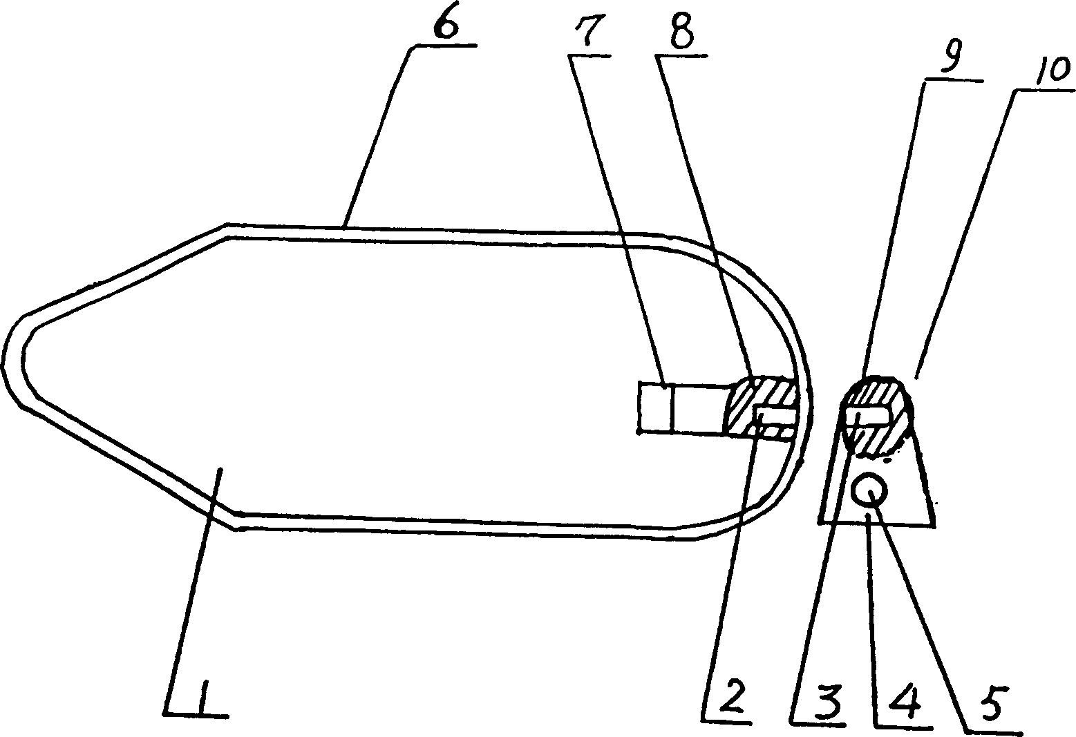
[0005] The present invention and its beneficial effects will be further described below in conjunction with the embodiments and accompanying drawings. figure 1 It is a schematic diagram of the structure of this embodiment. like figure 1 As shown, a magnetic shuttle auxiliary device for a circular loom, the shuttle 1 is arranged in the circumferential track, the push block 4 is connected with the main shaft through the push rod 5, there is a permanent magnet 2 at the tail of the shuttle 1, and the permanent magnet 2 is fixed on the push block 4. Magnet 3, two adjacent magnetic poles of permanent magnet 2 and permanent magnet 3 have the same name as magnetic poles. Also have a non-magnetic wire guide frame 6 to be contained in the periphery of shuttle 1, and an aluminum alloy integral back support 7 is also housed at the shuttle 1 afterbody, and its front part of described back support 7 is a large roller support. Load onto eccentric fixed wheel 8 above rear support 7. The pe...


PUM


Abstract

The invention provides circular loom magnetic shuttle power assistance unit, comprising the following solving scheme: the shuttle is settled in the orbit of a circle; the pushing bodies is connected with principal axis through handspikes; in the rump of the shuttle there are permanent-magnets which are fixed in the pushing bodies and the two poles of the permanent-magnets nearby are of the same homonymy; there is a nonmagnetic lead-thread frame is equipped outside of the shuttles and in the rump of the shuttle there is an aluminium alloy back bracket, and upon the back bracket there is a eccentric fixed wheel. The invention is simple in the structure, convenient to use, hard to see the phenomenon of silk breaking, improves the efficiency of loom, and suits for any type of looms.

Description

technical field [0001] The invention relates to a circular loom device, in particular to a magnetic shuttle auxiliary device for a circular loom. Background technique [0002] At present, the circular loom must complete two movements in the process of weaving the cylindrical bag cloth: the one is that the shuttle moves in a circle, and the other is that the weaving warp threads are interwoven up and down. The circular motion of the shuttle is driven by the rotation of the main shaft of the machine to drive the push rod and the shuttle pushing device, and then the shuttle pushing device pushes the shuttle to move along the circular orbit to complete. When weaving warp yarn up and down interweaving motion, weaving warp yarn must pass between pushing shuttle devices. Because there is no distance between the push shuttle device and the shuttle, when the weaving warp thread passes, the resistance is very large. In order to reduce the resistance when the weav...

Claims


Application Information

Patent Timeline
Patent Type & Authority Applications(China)
IPC IPC(8): D03D49/44D03D37/00
Inventor 唐欢利
Owner 唐欢利
Learn More