Pulsometer pump

A water pump and air pressure technology, applied in pressure pumps, mechanical equipment, machines/engines, etc., can solve problems such as waste and energy waste

Inactive Publication Date: 2006-06-21
张延胜
View PDF1 Cites 2 Cited by
  • Summary
  • Abstract
  • Description
  • Claims
  • Application Information

AI Technical Summary

Problems solved by technology

[0002] Patent No. 200510043213.3 in the prior art discloses an air pressure pump, which includes two casings with inlet and outlet ports and air inlet and exhaust control mechanisms and control exhaust mechanisms. The air inlet is provided with an air intake pipe and an air intake valve plug. The mouth of the air intake pipe is matched with the air intake valve plug. The air inta

Method used


Image

  • Pulsometer pump

Examples


Embodiment Construction

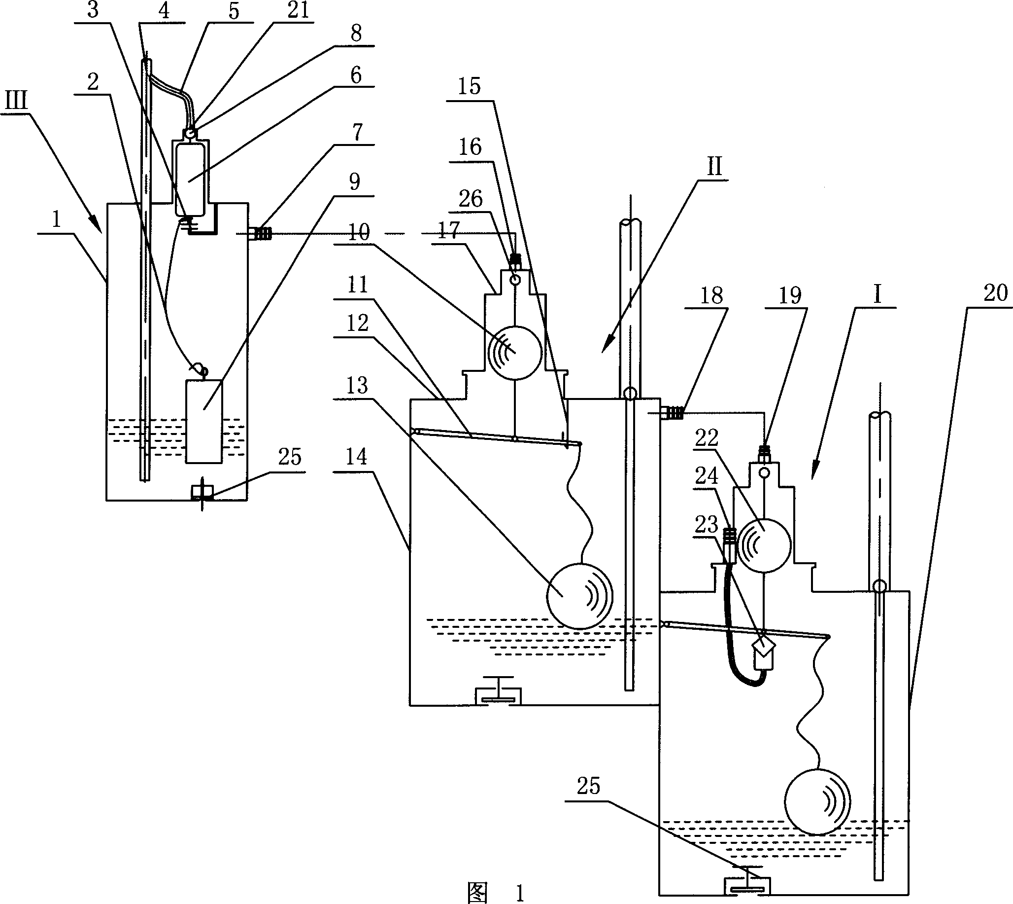
[0011] In order to clearly illustrate the technical features of the solution, the solution will be described below through a specific implementation mode combined with the accompanying drawings.

[0012] As shown in Figure 1, a kind of air pressure pumping machine, it comprises a water inlet 25, drainpipe 4 and air inlet 24, exhaust port 19 and control air intake mechanism 23 and control exhaust mechanism 22 primary pumping The casing 20 of I is characterized in that: the exhaust port 19 of the first-stage pumping water I communicates with the air inlet 18 of the casing 14 of the secondary pumping water II with the water inlet 25, the drain pipe 4, and the exhaust port 16, The casing 14 of the secondary pumping II is provided with a control exhaust mechanism. The control exhaust mechanism of the box body 14 of the secondary water pumping II includes a float valve housing 17 installed on the upper cover plate 12 of the box body 14. There is an exhaust valve corresponding to the...


PUM


Abstract

This invention relates to one gas pressure water lift machine in water engineer field, which comprises the following process: It has one water-in mouth, exit moth and gas-in mouth, exhaust mouth and control gas structure and exit control structure. The invention is characterized by the following: the gas-in mouth of first degree water lift and secondary water lift exhaust mouth are connected and the secondary water lift case exhaust mouth is connected to the secondary water lift exhaust tube through guide tube; the secondary water lift case is set with exhaust control structure.

Description

technical field [0001] The invention relates to a water conservancy machine, in particular to a pneumatic water pump. Background technique [0002] Patent No. 200510043213.3 in the prior art discloses an air pressure pump, which includes two casings with inlet and outlet ports, air inlet and exhaust control mechanisms and control exhaust mechanisms. The air inlet is provided with an air intake pipe and an air intake valve plug. The mouth of the air intake pipe is matched with the air intake valve plug. The air intake valve plug is connected with the control exhaust mechanism. The invention provides an automatic control with flexible and reliable Well, the cost is low and the air compressor can effectively control the air intake, but when the water tank is exhausted after the tank stops draining, the air pressure of the discharged gas is wasted, resulting in a great waste of energy. Contents of the invention [0003] The present invention aims at the disadvantages of the p...

Claims


Application Information

Patent Timeline
IPC IPC(8): F04F1/10
Inventor 张延胜张传松
Owner 张延胜
Why Eureka
Try Eureka