Direct-injection type centripetal gas inlet waste heat utilization device

A waste heat and air inlet technology, applied in non-variable-capacity engines, blade support elements, engine elements, etc., can solve the problems of energy loss, waste of resources, waste of energy, etc., and achieve the effect of making full use of energy and low resistance

Inactive Publication Date: 2015-05-13
张朝刚 +1
View PDF7 Cites 2 Cited by
  • Summary
  • Abstract
  • Description
  • Claims
  • Application Information

AI Technical Summary

Problems solved by technology

[0002] Existing engines often produce a large amount of waste heat when they are in operation, and these waste gases with a large amount of heat energy are discharged into the atmosphere, wasting resour

Method used


Image

  • Direct-injection type centripetal gas inlet waste heat utilization device
  • Direct-injection type centripetal gas inlet waste heat utilization device
  • Direct-injection type centripetal gas inlet waste heat utilization device

Examples


Embodiment Construction

[0013] The present invention will be further described below in conjunction with the accompanying drawings.

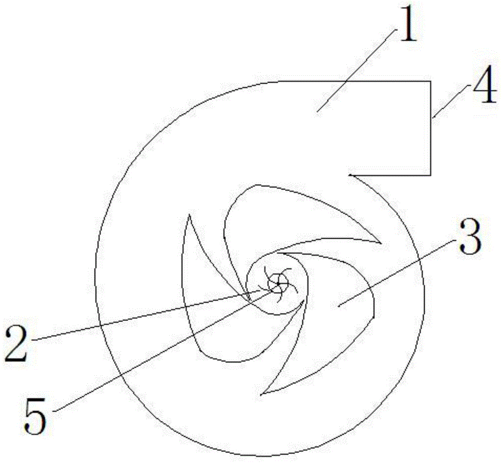
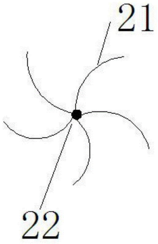
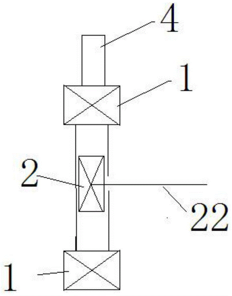
[0014] Such as Figure 1-3 As shown, a direct-type centripetal air intake waste heat utilization device includes a centripetal air intake structure 1, and the centripetal air intake structure 1 includes a snail shell, an air inlet 4 at the head of the snail shell, a snail The air outlet 5 on the side of the type shell, the central circle inside the shell, and several blades 3 arranged on the outer surface of the central circle, the blades have an arc-shaped structure that guides the airflow outside the central circle to the central circle; the gas enters Inside the centripetal air intake structure, it rotates along the stationary tangential blades, and enters the center circle through the gap between the blades to rotate. After passing through the centripetal tangential air intake structure, the rotating airflow is transmitted to the external equipment through the air ...


PUM


Abstract

The invention provides a direct-injection type centripetal gas inlet waste heat utilization device. The direct-injection type centripetal gas inlet waste heat utilization device comprises a centripetal gas inlet structure which comprises a snail-type shell, a gas inlet in the head of the snail-type shell, a gas outlet in the side face of the snail-type shell, a center circle in the shell and a plurality of blades arranged on the outer surface of the center circle, and the blades are provided with arc-shaped structures for guiding gas flow outside the center circle into the center circle. The direct-injection type centripetal gas inlet waste heat utilization device is characterized by comprising a gas turbine arranged in the center circle of the centripetal gas inlet structure, and shaft power is acquired through the gas turbine; a gas outlet is formed in the outer side of the center circle, and the diameter of the gas outlet is smaller than that of the center circle. Waste gas forms gas flow rotating at a high speed through the guide blades after entering the device through the centripetal gas inlet structure, the gas flow directly impacts the blades of the gas turbine to enable the gas turbine to rotate, the shaft power is acquired, and therefore the waste gas heat energy is recycled, and energy sources are fully utilized.

Description

technical field [0001] The invention relates to a waste heat recycling device, in particular to a direct-ray centripetal intake waste heat utilization device. Background technique [0002] Existing engines often produce a large amount of waste heat when they are in operation, and these waste gases with a large amount of heat energy are discharged into the atmosphere, wasting resources. The existing centripetal air intake type waste heat utilization device connects the centripetal air intake structure and the gas turbine through pipes, and there is energy loss in the middle, which wastes energy. Contents of the invention [0003] Aiming at the problems existing in the prior art, the present invention provides a direct-injection centripetal intake waste heat utilization device. When exhaust gas passes through the centripetal intake structure, under the action of guide vanes, a high-speed rotating airflow is formed, and the airflow directly impacts The blades of the gas turb...

Claims


Application Information

Patent Timeline
IPC IPC(8): F01D1/02F01D25/24F01D5/14
Inventor 张朝刚张立叶
Owner 张朝刚
Why Eureka
Try Eureka