Hydrogen power generation system

A power generation system, hydrogen technology, applied in the field of power generation systems based on hydrogen energy transmission, can solve the problems of air kinetic energy and pressure not being utilized, achieve high kinetic energy and improve work efficiency

Active Publication Date: 2020-02-14
安徽伯华氢能源科技有限公司
View PDF34 Cites 2 Cited by
  • Summary
  • Abstract
  • Description
  • Claims
  • Application Information

AI Technical Summary

Problems solved by technology

[0008] The technical problem to be solved by the present invention is: how to solve the problem that the kinetic energy and pressure energy of the air in the high-pressure hydrogen are not utilized

Method used


Image

  • Hydrogen power generation system
  • Hydrogen power generation system

Examples


Embodiment 2

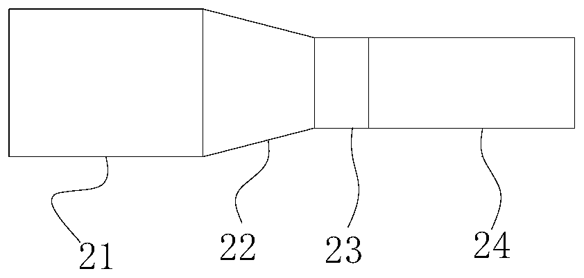
[0045] Such as figure 2 As shown, the specific structure of the Venturi tube 2 in this embodiment is: the Venturi tube 2 includes an inlet section 21 , a contraction section 22 , a throat 23 and a straight section 24 connected in sequence.

[0046] The diameter of the straight section 24 is the same as that of the throat 23. Specifically, the inlet section 21 is a short cylindrical section with a diameter of D; the shape of the constricted section 22 is a tapered tube with a cone angle of is 21°±2°; the throat 23 is a short straight pipe section with a diameter of about 1 / 3~1 / 4D, and the length is equal to the diameter of the pipe; the diameter of the straight section 24 is equal to the diameter of the circle of the throat 23 Tube.

[0047] By changing the diffusion section of the traditional Venturi tube 2 into a straight section 24, high-speed hydrogen with high kinetic energy can be obtained.

Embodiment 3

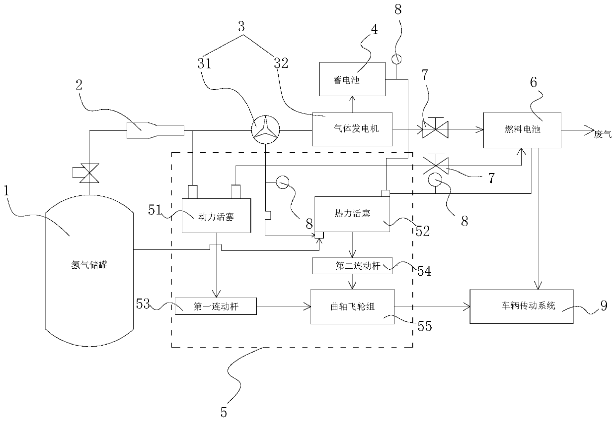
[0049] Such as figure 1 As shown, on the basis of Embodiment 2, this embodiment also includes two gas pressure stabilizing valves 7, one gas stabilizing valve 7 is installed between the wind power generator 32 and the fuel cell 4, and one gas stabilizing valve 7 is installed Between the power piston 51 and the fuel cell 4 .

[0050] Two gas stabilizing valves 7 keep the gas entering the fuel cell 4 at 1.5 atmospheres. In order to allow the fuel cell to absorb hydrogen more efficiently and increase the hydrogen utilization efficiency.

[0051] Concrete work process of the present invention is as follows:

[0052] S1. After the pressurized hydrogen flow in the hydrogen storage tank 1 enters the improved venturi tube 2, the hydrogen flow velocity increases and the pressure decreases;

[0053] S2. The hydrogen flow is divided into two parts, one part generates electricity through the wind power generator set 3, and the generated electric energy is stored in the storage battery ...


PUM

PropertyMeasurementUnit
angleaaaaaaaaaa

Abstract

The invention discloses a hydrogen power generation system comprising a hydrogen storage tank, a Venturi tube, a gas generator set, a fuel cell, an engine unit and a battery; the hydrogen storage tankis connected with the Venturi tube connected with the gas generator set, and the gas generator set is connected with the battery and the fuel cell separately; the fuel cell is connected with a vehicle transmission system; the engine unit comprises a power piston, a heating power piston and a transmission component, and the power piston is connected with the transmission component; the heating power piston is connected with the transmission component connected with the vehicle transmission system; the Venturi tube is further connected with the power piston connected with the fuel cell; the heating end of the heating power piston is connected with the battery and the fuel cell; and the cooling end of the heating power piston is connected with the gas generator set. The hydrogen power generation system has the beneficial effects that hydrogen energy is utilized fully, and the working efficiency is improved.

Description

technical field [0001] The present invention relates to a power generation system, in particular to a system based on hydrogen drive power generation. Background technique [0002] According to statistics, 60% of urban air pollution comes from motor vehicle exhaust emissions. Therefore, it is the general trend for new energy vehicles to gradually replace traditional fuel vehicles. Among the technical routes of various new energy vehicles, electric vehicles represented by hybrid vehicles, pure electric vehicles and fuel cell vehicles are generally considered to be the main direction for the transformation and development of future automotive energy and power systems, and have become the world's automotive powerhouse and major automotive industry. Manufacturer development focus. [0003] Compared with lithium battery electric vehicles, the most obvious advantage of using fuel cells is that it does not require a long charging process, and only needs a few minutes of hydrogenat...

Claims


Application Information

Patent Timeline
Patent Type & Authority Applications(China)
IPC IPC(8): F01B23/02F01D15/10F02G1/043H01M8/04089F17C1/00B60L50/70
CPCB60L50/70F01B23/02F01D15/10F02G1/043F17C1/00H01M8/04089Y02E60/32Y02E60/50Y02T90/40
Inventor 刘青王广华孟双红祝妍马凯成张晓岭刘骏坤杨培
Owner 安徽伯华氢能源科技有限公司
Why Eureka
Try Eureka