Network transmission method for multi-protocol label exchange VPN
A technology of multi-protocol labeling and switching virtualization, applied in the network transmission field of multi-protocol label switching virtual private network, can solve the problems of inconvenient upgrade and expansion, heavy control plane workload, complex processing flow, etc. Easy to operate, easy to operate effect
- Summary
- Abstract
- Description
- Claims
- Application Information
AI Technical Summary
Problems solved by technology
Method used
Image

Examples
Embodiment 1
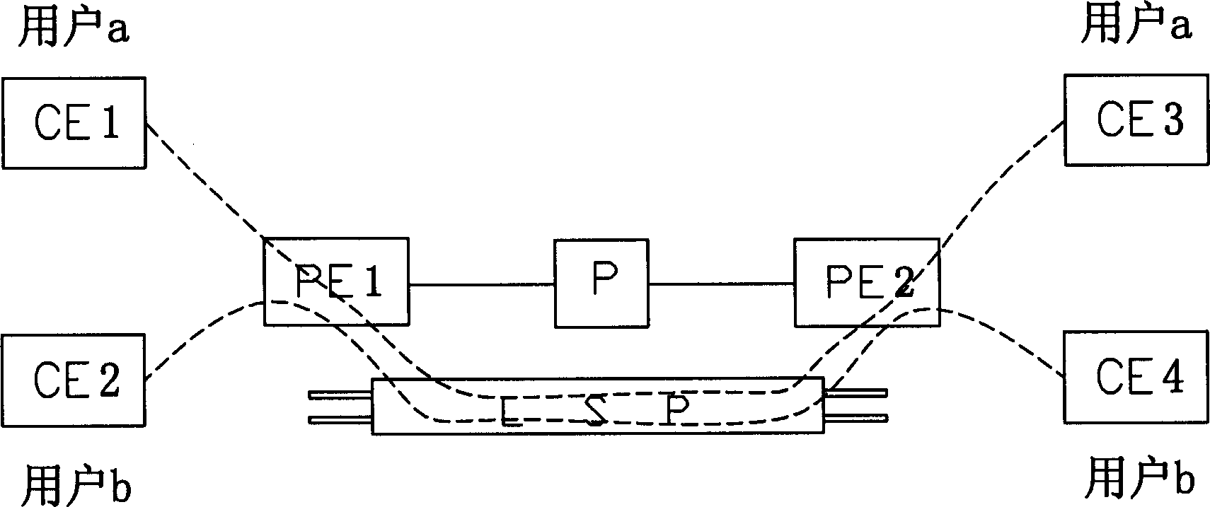
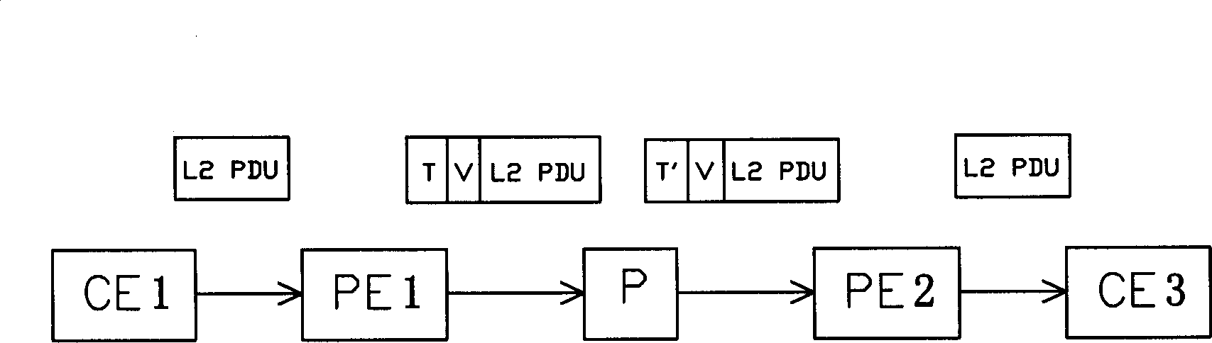
[0055] Such as image 3 As shown, the provider edge PE1 node, the provider edge PE2 node and the P device (P device: core forwarding node device) form a multi-protocol label switching virtual private network, and the provider edge PE1 node and the provider edge PE2 establish A label switching path LSP1 is established, the customer edge CE1 terminal and the customer edge CE2 terminal that establish a virtual connection VC with the provider edge PE1 node are provided to user a and user b respectively, and the customer edge CE3 terminal that establishes a VC connection with the provider edge PE2 node and the CE4 terminal at the customer edge are respectively provided to user a and user b, and the different VC packets of user a and user b are transmitted through the same label switching path LSP1 tunnel, for example Figure 5 As shown in the figure, the message of the customer edge CE1 terminal is connected to the data plane through the data interface, and the virtual connection V...
Embodiment 2
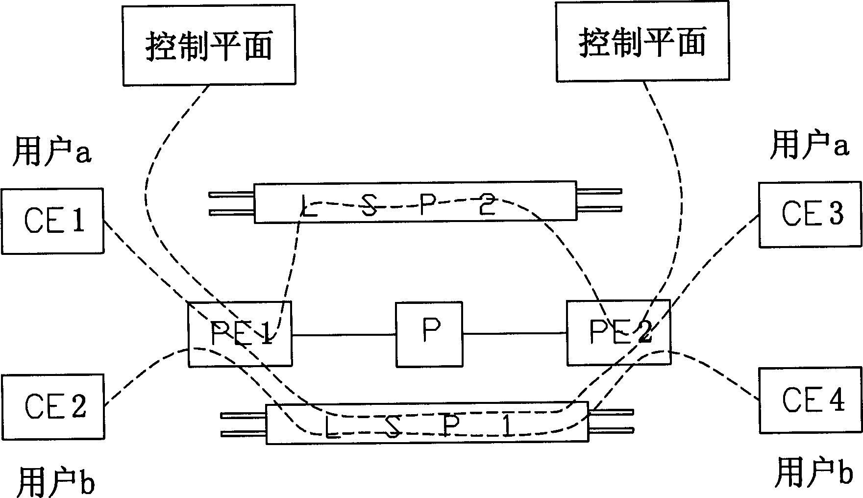
[0070] Such as Figure 6 As shown, the difference between this embodiment and Embodiment 1 is that in this embodiment, the MPLS VPN specifies an existing label switching path LSP1 tunnel as the control plane between different provider edge PE nodes information transmission channels, such as Figure 6 As shown, the control plane shares the label switching path LSP1 tunnel with user a and user b, so as to establish an information transmission channel between the control planes. As for the specific control process of this embodiment is the same as or similar to that described in Embodiment 1, it will not be repeated here.
Embodiment 3
[0072] according to Figure 7 and Figure 8 ,refer to image 3 , the overall structure of this embodiment is the same as that of Embodiment 1, and the specific control flow of this embodiment is as follows:
[0073] 1. If image 3 and Figure 7 As shown, the MPLS virtual private network allocates virtual connection VC labels for the control plane, establishes virtual connection VCs at the provider edge PE1 node and provider edge PE2 node, and the control plane and the corresponding provider edge PE1 node, provider edge The PE2 node establishes a virtual connection VC. In the present invention, in view of the application complexity of the control plane, corresponding virtual connection VC labels can be allocated according to different modules or applications in the control plane, that is, the division of the forwarding equivalence class FEC can be based on different A module or an application allocates multiple virtual connection VC labels to the control plane. Create a ne...
PUM
 Abstract
Description
Claims
Application Information
 - R&D
- Intellectual Property
- Life Sciences
- Materials
- Tech Scout
- Unparalleled Data Quality
- Higher Quality Content
- 60% Fewer Hallucinations
Browse by: Latest US Patents, China's latest patents, Technical Efficacy Thesaurus, Application Domain, Technology Topic, Popular Technical Reports.
© 2025 PatSnap. All rights reserved.Legal|Privacy policy|Modern Slavery Act Transparency Statement|Sitemap|About US| Contact US: help@patsnap.com