Eddy current type reduction gear

A reducer and eddy current technology, applied in the field of eddy current reducer, can solve problems such as sliding braking and magnetic flux leakage

Inactive Publication Date: 2006-06-21
ISUZU MOTORS LTD
View PDF2 Cites 5 Cited by
  • Summary
  • Abstract
  • Description
  • Claims
  • Application Information

AI Technical Summary

Problems solved by technology

However, if the magnetic force of the magnets 61, 62 is increased, a problem arises that part of the magnetic flux

Method used


Image

  • Eddy current type reduction gear
  • Eddy current type reduction gear
  • Eddy current type reduction gear

Examples


Embodiment Construction

[0046] Preferred embodiments according to the present invention will be described below with reference to the accompanying drawings.

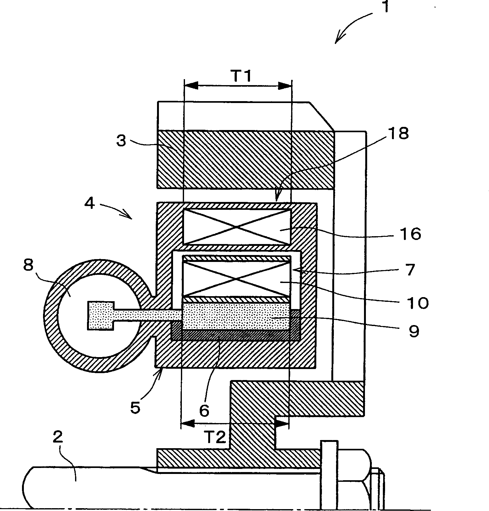
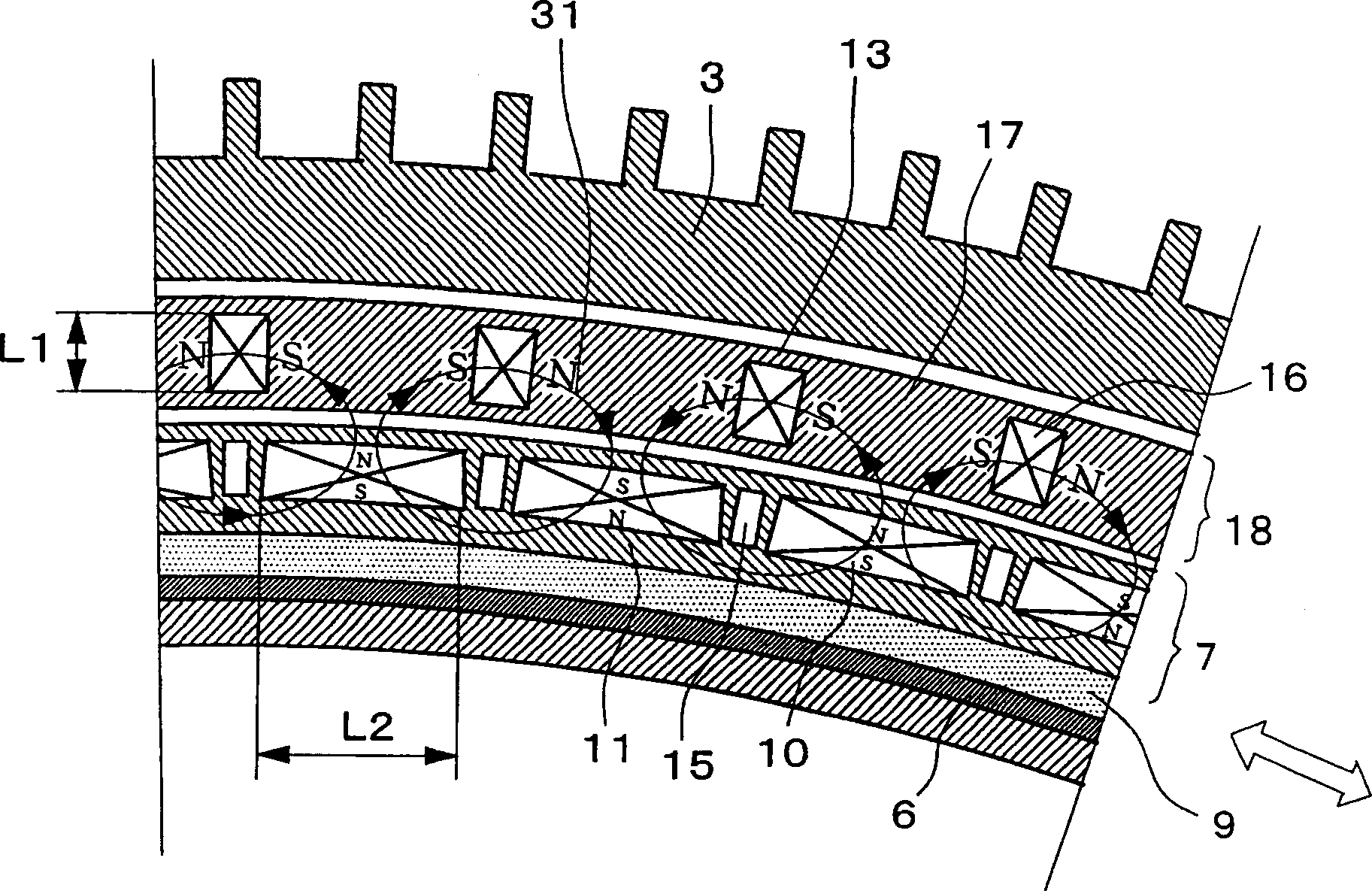
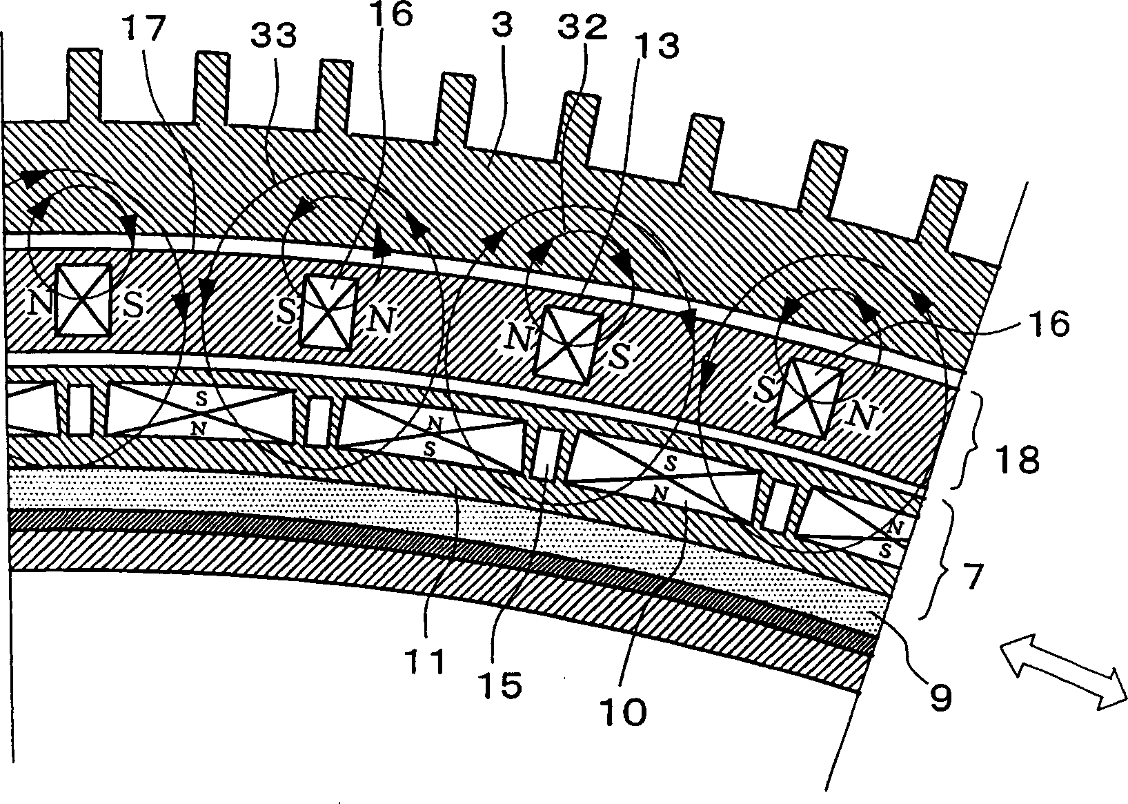
[0047] figure 1 is a side sectional view of the upper half of the eddy current type speed reducer according to the present invention. figure 2 is a partial front sectional view showing the state of the eddy current speed reducer during a braking stop. image 3 is a partial front sectional view showing the state of the eddy current reducer during brake activation.

[0048] Such as figure 1 As shown, the eddy current speed reducer 1 includes a drum-shaped brake rotor 3 mounted on a rotating shaft 2 such as a vehicle drive shaft, and a drum-shaped brake rotor 3 radially arranged on the inner side of the brake rotor 3 and installed in such as a transmission box, etc. Stator 4 (source of magnetic force) on the fixed side. The deceleration braking of the rotating shaft 2 is induced by supplying magnetic force from the stator 4 to the rotor 3 t...


PUM


Abstract

An object of the present invention is to provide an eddy current type speed reducer capable of securing braking capability and preventing leakage of magnetic force. In a preferred embodiment of the present invention, the eddy current reducer (1) includes a first magnet ring ( 18), and the second magnet ring (7) that is arranged opposite to the first magnet ring (18) and includes a plurality of permanent magnets (10) spaced along the circumferential direction, wherein the second magnet ring (7 The magnetic force of each permanent magnet (10) of ) is set to be greater than the total of one or more permanent magnets (16) of the first magnet ring (18) used as a cooperating part of the magnetic circuit in the braking stop state magnetic force. As a result, the magnetic flux leakage to the brake rotor (3) during the braking stop can be almost zero.

Description

technical field [0001] The present invention relates to an eddy current type speed reducer mainly suitable for use as a secondary brake of a large vehicle. Background technique [0002] Eddy current speed reducers have been used as secondary brakes for large vehicles such as trucks. [0003] see below Figure 15 and Figure 16 An example of a conventional eddy current type speed reducer will be described. [0004] The eddy current speed reducer 51 includes a drum-shaped brake rotor 53 installed on a rotating shaft 52 such as a vehicle drive shaft, and a drum-shaped brake rotor 53 arranged radially inside the brake rotor 53 and mounted on a fixed side such as a transmission case. Stator 54 (magnetic force source). [0005] The stator 54 comprises a hollow housing 55 supported on the fixed side and two magnet rings 57 , 58 arranged inside the housing 55 . [0006] The first magnet ring 57 is fixed so that it cannot rotate relative to the housing 55, and the second magnet r...

Claims


Application Information

Patent Timeline
IPC IPC(8): H02K49/10H02K49/02
Inventor 桑原彻小川诚
Owner ISUZU MOTORS LTD
Why Eureka
Try Eureka