Method of driving liquid crystal display and liquid crystal display

A technology of a liquid crystal display device and a driving method, which is applied to static indicators, nonlinear optics, instruments, etc., can solve the problems of brightness increase, contrast decrease, and the inability to fully ensure the writing time of pixel electrode charge, that is, the charging period, etc. Horizontal line unevenness, the effect of ensuring charging time

Inactive Publication Date: 2006-06-28
MITSUBISHI ELECTRIC CORP
View PDF3 Cites 2 Cited by
  • Summary
  • Abstract
  • Description
  • Claims
  • Application Information

AI Technical Summary

Problems solved by technology

In such a high-resolution liquid crystal display device, when the conventional driving method is adopted, the charge writing time to the pixel electrode, that is, the charging period, cannot be sufficiently ensured, for example, when driving the liquid crystal panel using the always bright liquid crystal mode. , there is a problem that the brightness increases and the contrast decreases when the full black screen is displayed

Method used


Image

  • Method of driving liquid crystal display and liquid crystal display
  • Method of driving liquid crystal display and liquid crystal display
  • Method of driving liquid crystal display and liquid crystal display

Examples


Embodiment 1

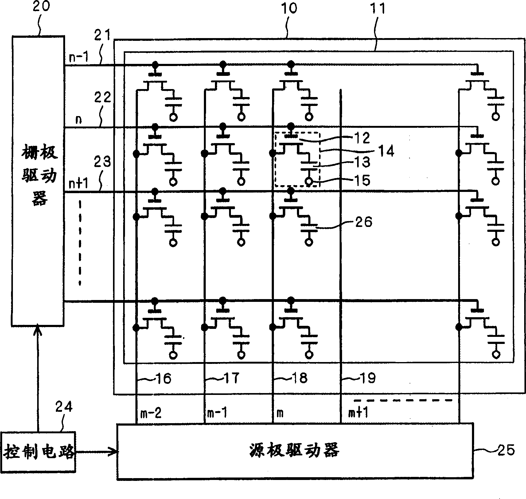
[0016] figure 1 It is a configuration diagram showing a liquid crystal display device controlled by implementing the driving method of Embodiment 1 of the present invention. figure 1 Among them, the always bright liquid crystal panel 10 is composed of a plurality of source wirings 16, 17, 18, 19 crossing each other and a plurality of gate wirings 21, 22, 23 in an active matrix substrate 11 formed in a matrix, and the The counter substrate (not shown) facing the active matrix substrate 11 is pasted with a gap, and a liquid crystal (not shown) is sandwiched between the gap. Here, the pixel portion 14 indicated by a dotted line is arranged at the intersection of the source wirings 18, 19 and the gate wirings 22, 23, a TFT 12 and a pixel electrode 13 are provided as switching elements, and the gate of the TFT 12 is connected to the gate wiring 22. The source is connected to the source wiring 18 , and the drain is connected to the pixel electrode 13 . In addition, the pixel ele...

Embodiment 2

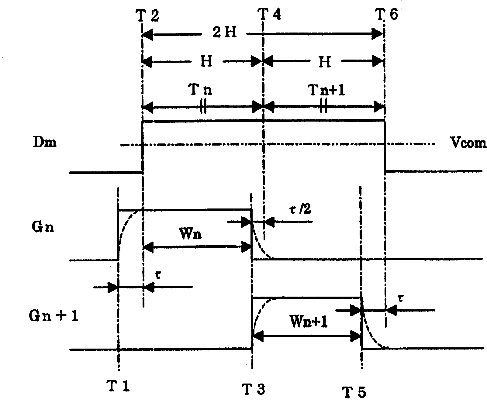
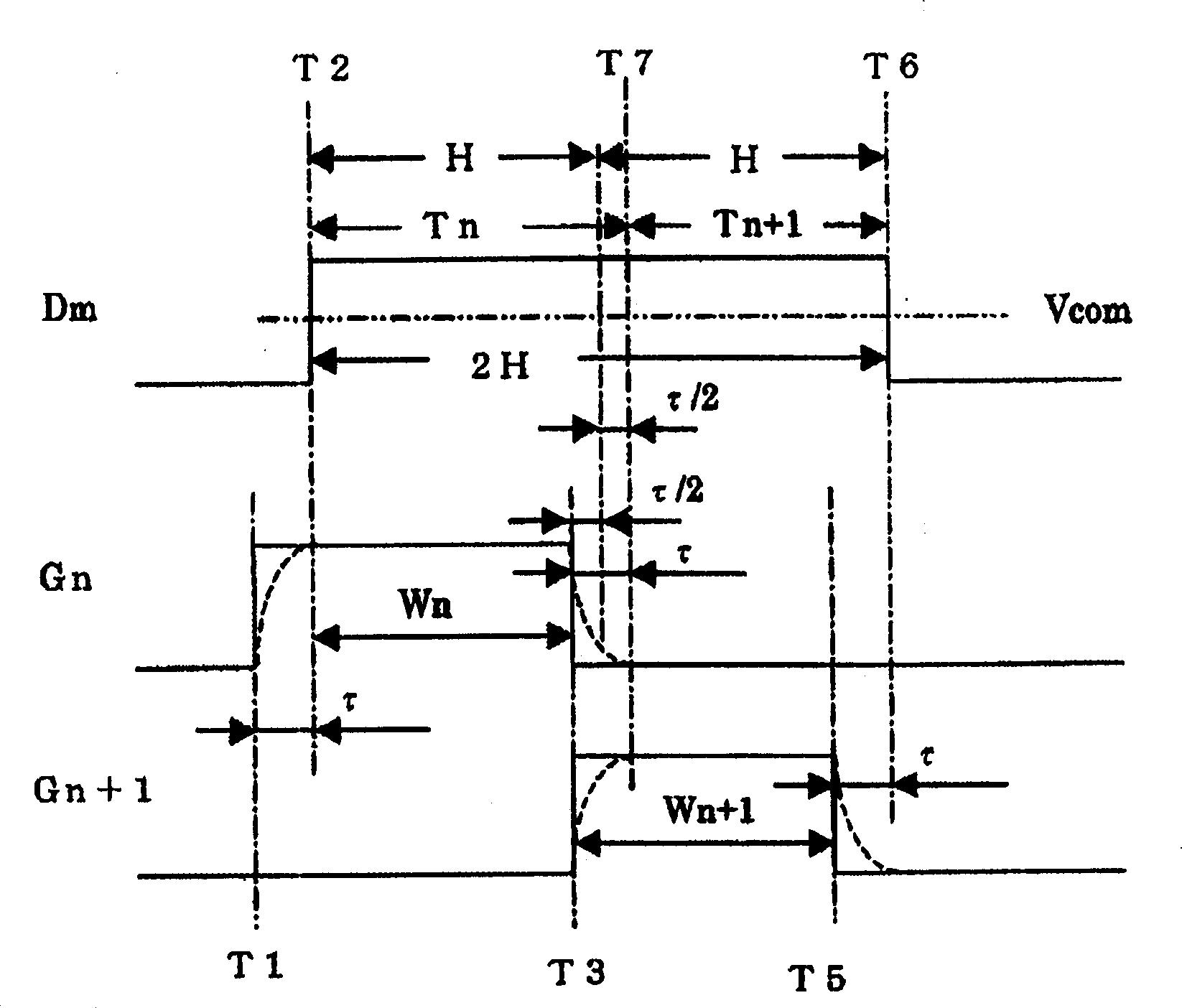
[0027] image 3 It is a timing chart showing a method of driving a liquid crystal display device according to Embodiment 2 of the present invention. In this embodiment 2, the above-mentioned embodiment 1 figure 2 The output switching time of the data signal Dm, that is, the time T4 is delayed by the period τ / 2 to be the time T7, and the period T3-T7, that is, the fourth period is taken as τ. That is, the period T5-T6, that is, the third period and the fourth period T3-T7 are set to have the same length τ. Others are the same as in Embodiment 1, so description is omitted.

[0028] Such as image 3 As shown, the signal output period of the data signal Dm is Tn=H+τ / 2, Tn+1=H−τ / 2. In Embodiment 2, the output switching time T7 of the data signal Dm is set to be delayed by only the period τ from the turning-off time T3 of the gate selection signal Gn as the fourth period. In addition to raster screen display, it is possible to suppress display unevenness caused by slowing down ...


PUM


Abstract

In the 2H line inversion driving method among the driving methods of the liquid crystal display device, etc., the time point (T2) indicating that the polarity of the data signal (Dm) is reversed to the time when the first gate selection signal (Gn) is turned off The first period (Wn) of the time interval up to the time point (T3) has the same time length as the second period (Wn+1) indicating the on-period of the second gate selection signal (Gn+1), and will indicate from The period from the time (T3) when the first gate selection signal is turned off to the time (T4) when the data signal (Dm) switches to the data output corresponding to the pixel selected by the second gate selection signal The time interval is set to be equal to or less than the time interval from the time (T5) when the second gate selection signal is turned off to the time (T6) when the polarity of the data signal is reversed. Accordingly, a high-resolution liquid crystal display device and a driving method thereof are provided with suppressed horizontal unevenness.

Description

technical field [0001] The present invention relates to a driving method for controlling the supply of a selection signal for controlling the conduction of a plurality of switching elements respectively connected to a plurality of pixel electrodes of a liquid crystal display device and a data signal supplied to a plurality of pixels via these switching elements, and having a The driving method is controlled by the control circuit of the liquid crystal display device. Background technique [0002] In a liquid crystal display device, the gate selection signal output from the gate driver to the gate wiring is slowed down by the wiring resistance of the gate wiring and the stray capacitance of the wiring, and the selection signal is delayed. As a countermeasure, it is well known that the timing at which the gate selection signal changes from on to off (hereinafter referred to as off) or from off to on (hereinafter referred to as on) is the same as that from the source driver to ...

Claims


Application Information

Patent Timeline
Patent Type & Authority Applications(China)
IPC IPC(8): G09G3/36G02F1/133G09G3/20
CPCG09G3/3614G09G3/3648G09G2310/08G09G2320/0223G09G2320/0233G09G3/36G02F1/133G09G3/20
Inventor 寺垣智哉中西邦文南昭宏
Owner MITSUBISHI ELECTRIC CORP
Why Eureka
Try Eureka