Parallel dispatching processing method in optical burst switched network

A technology of optical burst switching and burst data, which is applied to the selection device, electrical components, selection device, etc. of the multiplexing system. Bandwidth utilization capability and effect of improving latency performance

Inactive Publication Date: 2006-06-28
ZHEJIANG XUNBO INFORMATION ENG
View PDF0 Cites 5 Cited by
  • Summary
  • Abstract
  • Description
  • Claims
  • Application Information

AI Technical Summary

Problems solved by technology

[0006] The purpose of the present invention is to address the deficiencies of the existing JET protocol, using the source routing characteristics of the OBS network, to provide a new resource reservation protocol

Method used


Image

  • Parallel dispatching processing method in optical burst switched network
  • Parallel dispatching processing method in optical burst switched network
  • Parallel dispatching processing method in optical burst switched network

Examples


Embodiment Construction

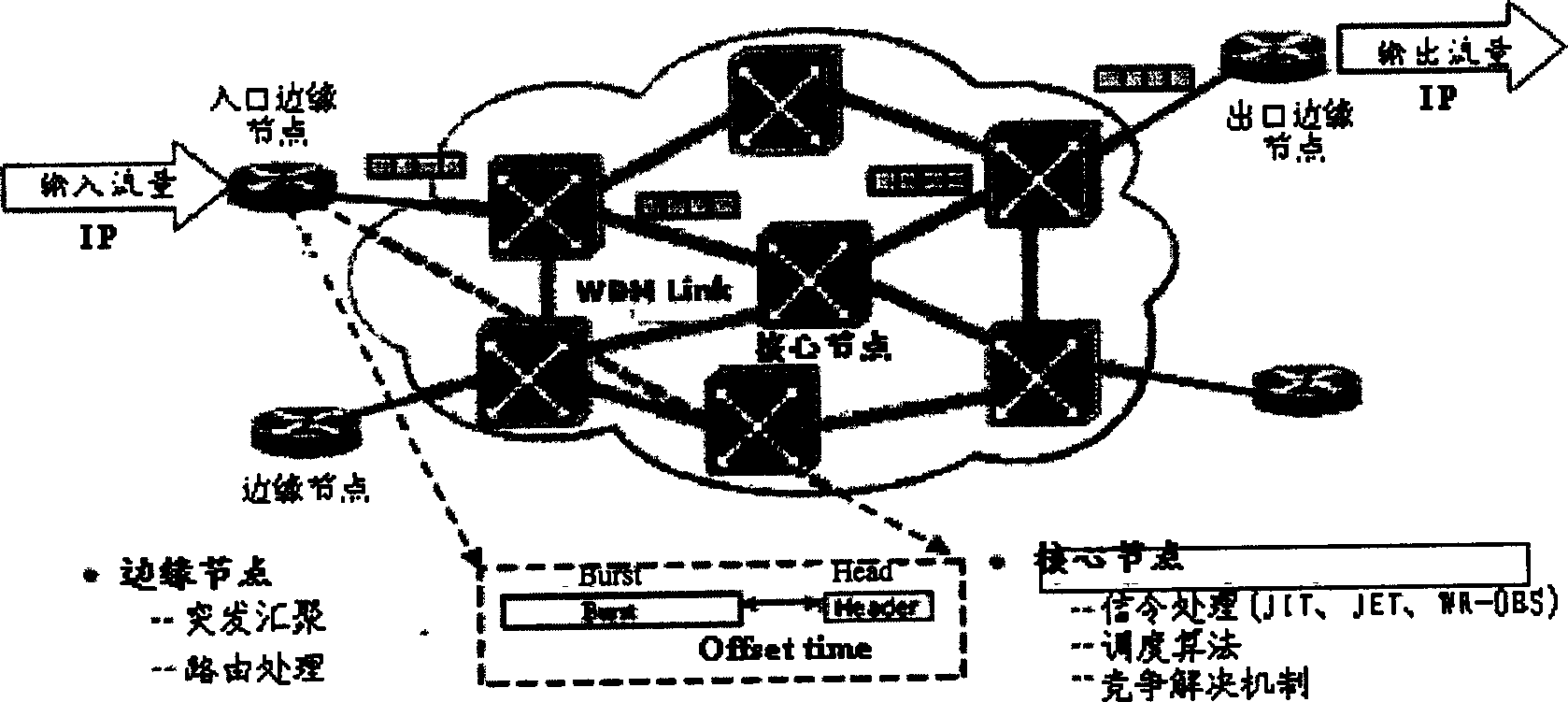
[0044] figure 1 The middle box indicates that the main innovative field of the present invention is signaling processing.

[0045] A core node architecture and workflow in the OBS system using the parallel scheduling method:

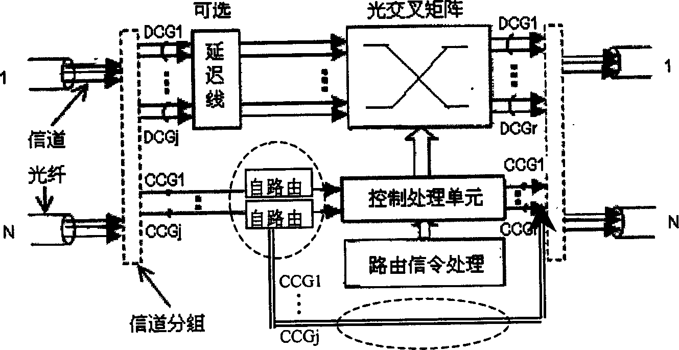
[0046] Such as figure 2 As shown, this method requires an increased self-routing function module.

[0047] The dotted box indicates the module unit that this method needs to add to the basic OBS core node architecture. In the figure, DCG (Data Channel Group) represents the data channel group, and CCG (Control Channel Group) represents the control channel group. The self-routing unit is set at the receiving end of the control channel, and adopts the routing method of all-optical single-bit address identification, which can control channel signaling Packets are replicated, forwarded and dropped to a local control processing unit.

[0048] The workflow of the system is as follows:

[0049] The edge node allocates a burst sequence identifier for the bu...


PUM


Abstract

This invention relates to a parallel dispatch method in a light burst exchange network, in which, when a core node receives a control frame containing resource preengaged information, it transmits said control frame to the next node timely in the mode of self-routing and routes another copy to the local area for resource preengaging process, the method also includes the following steps: the edge node generates a burst frame serial number with an only ID in a network to each due out datum relating to different kinds of related signaling frames belonging to a same data frame in the association method.

Description

technical field [0001] The invention relates to the field of optical burst switching network technology, in particular to a parallel scheduling processing method in the optical burst switching network. Background technique [0002] In recent years, IP services have maintained an explosive growth trend, which has triggered a lot of research on high-speed transmission and switching technologies. Dense wavelength division multiplexing (DWDM), the transmission technology of the next-generation IP core backbone network, provides support for a large number of high-speed channels on a single fiber, which means that a huge bandwidth is provided for the physical underlying transmission, but another On the one hand, the growth rate of the electrical processing rate is much lower than the growth rate of the transmission rate. If the data transmission of the node needs to be converted back to the electrical domain for exchange, the network transmission speed will encounter the bottlenec...

Claims


Application Information

Patent Timeline
IPC IPC(8): H04Q11/00
Inventor 李彦君张国清
Owner ZHEJIANG XUNBO INFORMATION ENG
Why Eureka
Try Eureka