
Membrane pipe module

A technology of modules and membrane tubes, applied in membrane, membrane technology, semi-permeable membrane separation, etc., can solve the problem of increased cost per unit membrane area for installation

Inactive Publication Date: 2006-06-28
SULZER CHEMTECH - MEMBRANTECHN
View PDF1 Cites 4 Cited by
  • Summary
  • Abstract
  • Description
  • Claims
  • Application Information

AI Technical Summary

Problems solved by technology

Therefore, the unavoidable limitation of the membrane area of ​​each module, the required number of intermediate heat exchangers, the necessary additional piping connections between these devices, and the additional expenditure for control have resulted in the cost of installing a unit membrane area. Increase

Method used


Image

  • Membrane pipe module
  • Membrane pipe module

Examples


Embodiment Construction

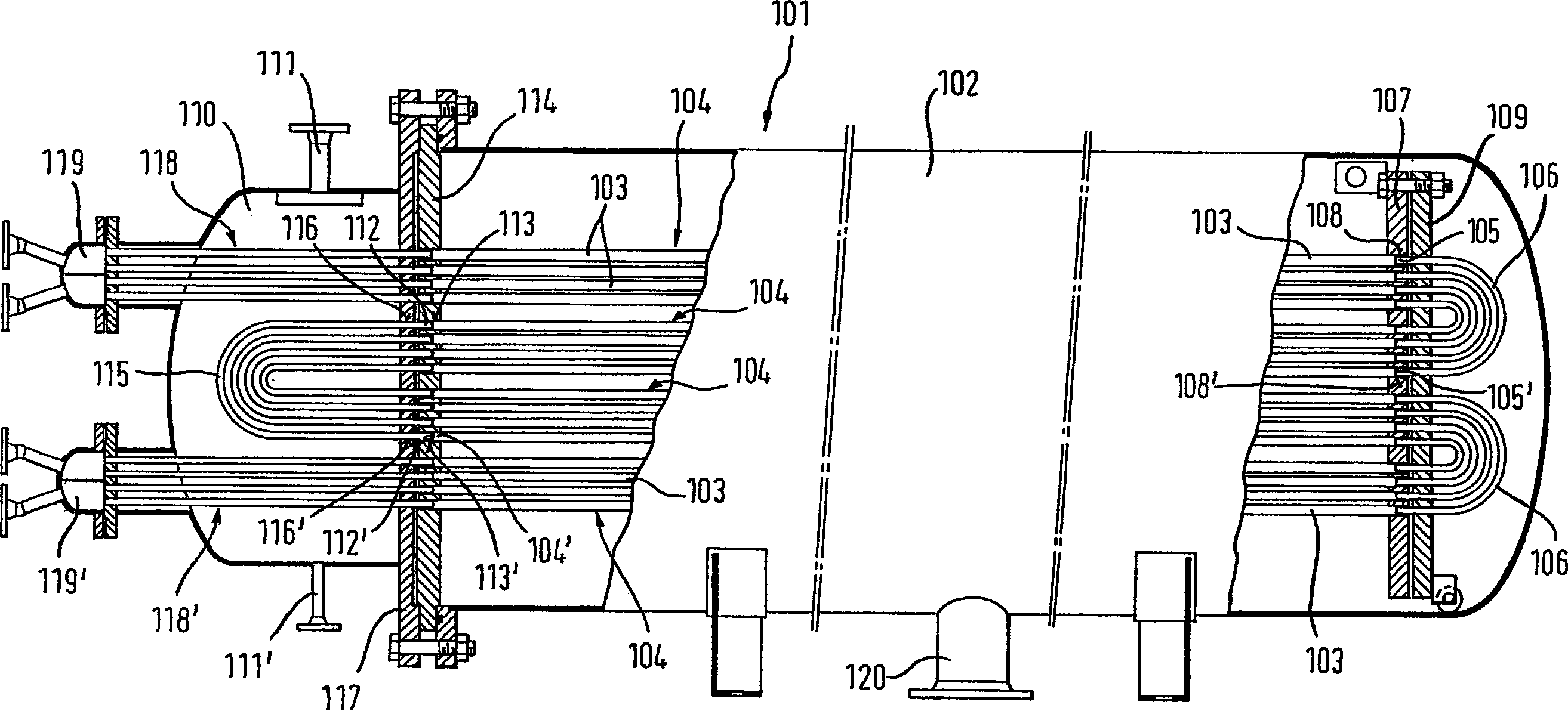
[0015] figure 1 The midtube assembly 101 has a cylindrical housing 102 containing a plurality of axially aligned support tubes 103 with tubular membrane sections 104 . In another embodiment (not shown), tubular membrane segments of sufficient compression resistance without support tubes are used. The cylindrical housing 102 is provided with at least one connection 120 for discharging the permeate that has passed through the membrane.

[0016] figure 1 Among them, on one side of the tube assembly 101, the corresponding one end 105 of the tubular membrane section 104 is fixed in the hole 108 of the separating wall 107, and is connected to the second tubular membrane section 104 fixed in the hole 108' of the separating wall 107 through a connector 106. The end 105' of the membrane segment 104'. exist figure 1 In , the connector 106 is a U-shaped tube, however it could also be a corresponding gap in the end plate 109 . Using this gap in the end plate 109, several tubular memb...


PUM


Abstract

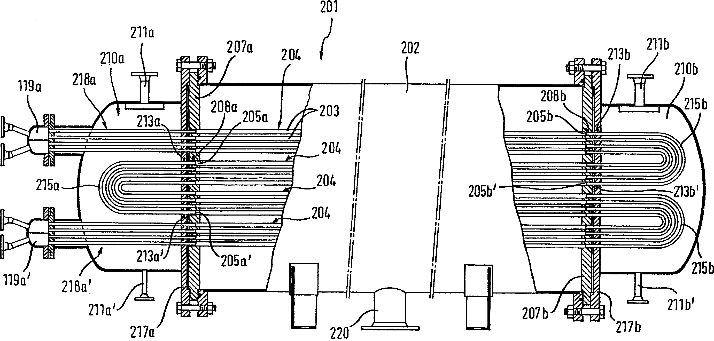
The invention relates to a membrane tube assembly, said assembly comprising a cylindrical housing (102) containing a plurality of tubular membrane portions (104) extending in the axial direction and having ends (105, 105' ) are connected to each other to form a longer tubular membrane part. The cylindrical housing (102) includes a heatable cavity (110) containing U-shaped connecting pipes (115) arranged on one or both sides of the cavity and passing through the cavity. The two open ends of the separation walls (117, 114) between the cavity (110) and the housing (102) are connected to two adjacent open tubular membrane parts (112, 112') respectively, forming a membrane circuit.

Description

technical field [0001] The present invention relates to a tube assembly comprising a tubular membrane and an integrated heat exchanger. Background technique [0002] Membranes used in membrane technology for the separation of liquid or gaseous mixtures are incorporated in modules in an efficient arrangement. Commonly known shapes of such modules are, on the one hand, flat-sheet modules with corrugated membranes and helically wound modules, and on the other hand, hollow-fiber, capillary, tubular or tube-like modules. Modules of the first type are used for membranes in the form of flat plates and modules of the second type are used for membranes in tubular form. The diameter of the individual tubular membranes varies from 30μ to 100μ for hollow fiber modules, 0.2mm to 3mm for capillary modules, and 4mm to 50mm for tubular or tube modules. The transmembrane flow is from the outside to the inside of the hollow fiber. In the capillary membrane, it can be from the outside to the...

Claims


Application Information

Patent Timeline
Patent Type & Authority Applications(China)
IPC IPC(8): B01D61/36B01D63/06B01D65/00
CPCB01D63/063B01D65/00B01D2313/13B01D2313/23B01D2319/022B01D61/3621B01D63/069
Inventor 帕特里克·尼古拉斯·淮恩弗兰克-克劳斯·马格拉夫哈特姆特·布与史科
Owner SULZER CHEMTECH - MEMBRANTECHN
Learn More