Receipt cabinet
A single cabinet and single cabinet technology, which is applied in the field of document access equipment, can solve the problems that the receipt cabinet occupies a large space and cannot be used through the wall, and achieves the effects of stable operation, reduced workload, and low failure rate
- Summary
- Abstract
- Description
- Claims
- Application Information
AI Technical Summary
Problems solved by technology
Method used
Image

Examples
Embodiment 1
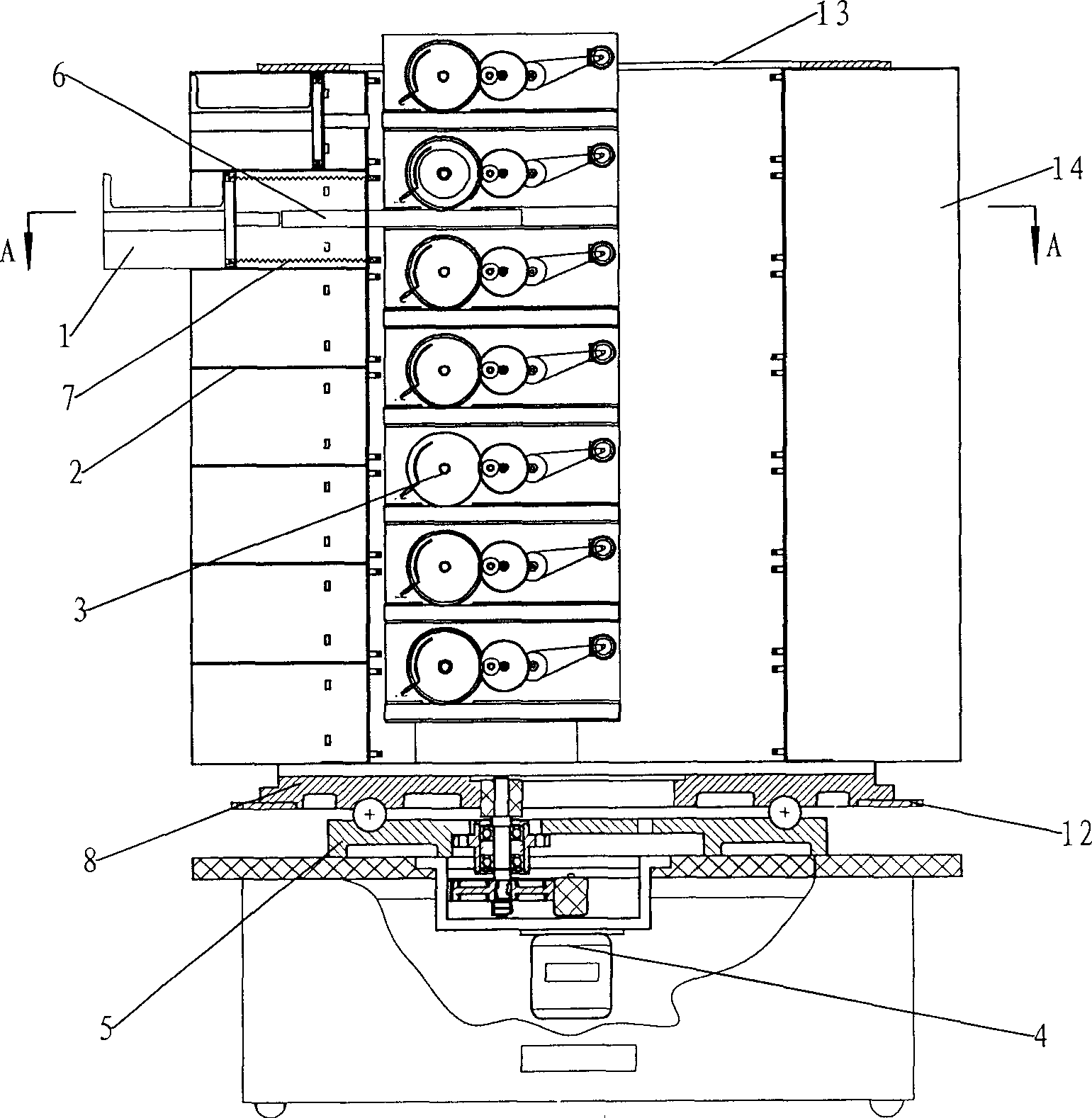
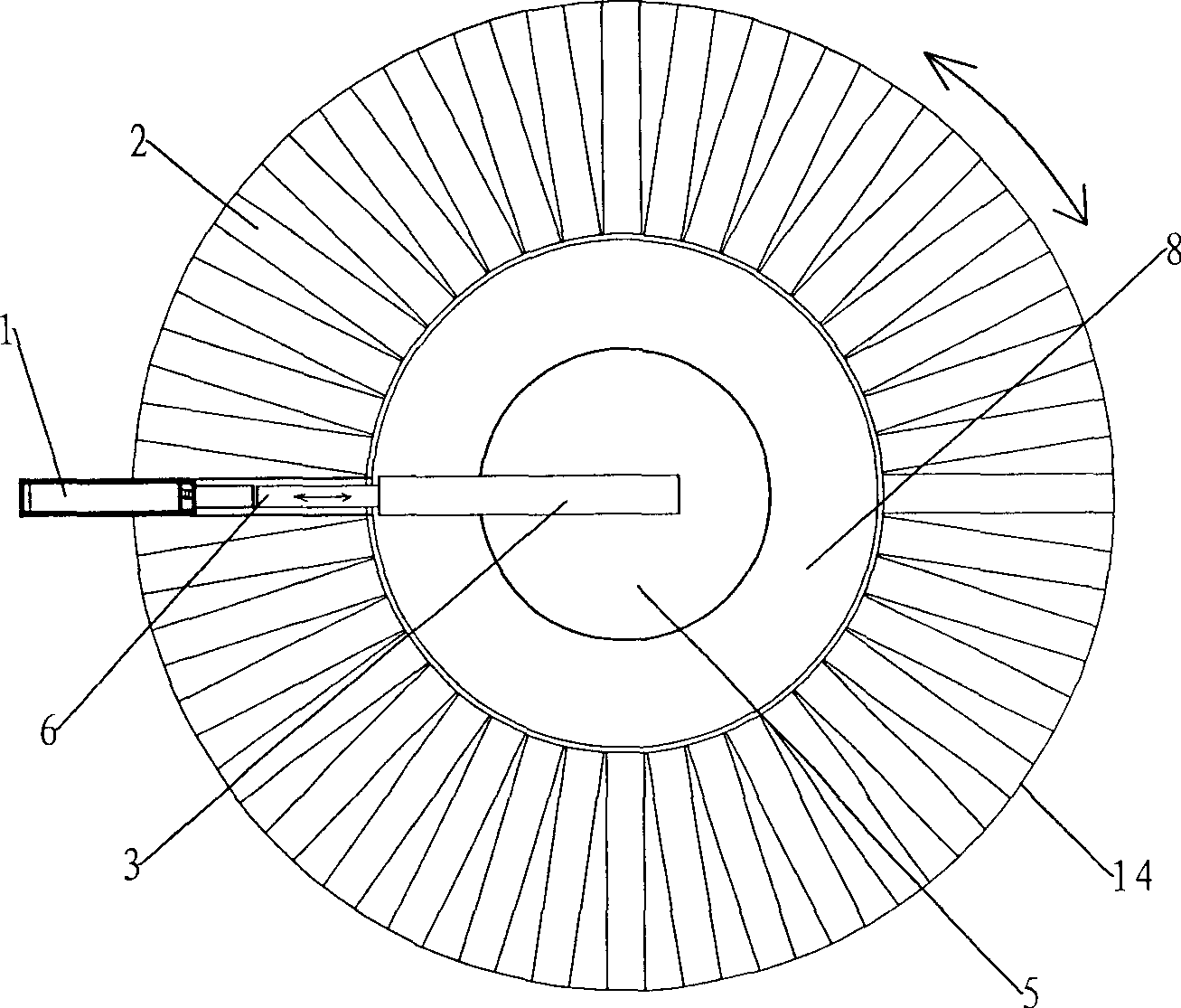
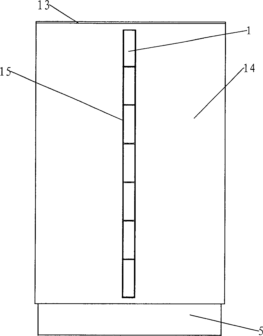
[0030] Embodiment 1: as Figure 1 ~ Figure 3As shown, the return order cabinet of the present invention includes a drawer 1 installed in a drawer box 2 and a drawer push-out mechanism 3 that pushes the drawer 1 to open and close. There are 40 drawer boxes 2 in total, and there are 7 drawers 1 in each drawer box 2, a total of 280 drawers 1. The 7 drawers 1 are vertically stacked up and down, and the drawer boxes 2 are installed on the bracket, which includes a base 5 1. The rotating base plate 8 that is arranged on the base 5 and rotates along the vertical fixed axis, the drawer box 2 is fixed on the rotating base plate 8 and arranged in a cylindrical shape around the rotation axis of the rotating base plate 8, and the top plate 13 is arranged on the top, so that the drawer box 2 is fixed Clamped between the rotating bottom plate 8 and the top plate 13, the drawer boxes 2 arranged around its circumference form a whole, as figure 1 , figure 2 As shown, a vertical revolving si...
Embodiment 2
[0035] Embodiment 2: as Figure 4~6 As shown, the return order cabinet of the present invention includes a drawer 1 installed in a drawer box 2 and a drawer push-out mechanism 3 that pushes the drawer 1 to open and close. There are 32 drawer boxes 2, and 8 drawers 1 are arranged in each drawer box 2, a total of 256 drawers. The direction in which the drawers 1 are arranged is that the left and right are stacked horizontally, and the drawer box 2 is installed on the support. The support includes a base 5, a horizontal shaft 10 arranged on the base 5, and a lantern-shaped shaft that is fixed on the horizontal shaft 10 and rotates along a horizontal fixed axis. The frame 9 and the drawer box 2 are fixed on the lantern-shaped frame 9 and arranged in a cylindrical shape around the rotation axis of the lantern-shaped frame 9, thereby forming a horizontal rotary single cabinet.
[0036] The drawer push-out mechanism 3 is arranged between the drawer box 2 and the drawer 1 so as to fo...
PUM
 Abstract
Description
Claims
Application Information
PatSnap Eureka turns technology decisions into work you can execute. Powered by our Innovation Knowledge Graph, it runs expert workflows across engineering, life sciences, materials and intellectual property. Get your review-ready output in minutes.


