
Printing correction unit and method for ink gun

A correction method and technology for a correction device, which are applied to printing devices, printing and other directions, can solve the problems of reducing printing speed, affecting printing speed, increasing printer cost, etc., and achieving the effect of improving printing skew and improving printing quality.

Inactive Publication Date: 2006-07-05
IND TECH RES INST
View PDF0 Cites 4 Cited by
  • Summary
  • Abstract
  • Description
  • Claims
  • Application Information

AI Technical Summary

Problems solved by technology

[0004] Known methods for calibrating inkjet head printing are implemented in software within the printer system, but this can overload the printer system and affect printing speed
And the application of this method must install an optical sensor on the printer, which increases the cost of the printer, and the known technology needs to increase the delay time outside the pulse time of each position, resulting in a reduction in printing speed

Method used


Image

  • Printing correction unit and method for ink gun
  • Printing correction unit and method for ink gun
  • Printing correction unit and method for ink gun

Examples


Embodiment Construction

[0044] In order to make the above-mentioned purpose, features and advantages of the present invention more obvious and understandable, the preferred embodiments of the present invention are specially enumerated below, and in conjunction with the attached drawings, the detailed description is as follows:

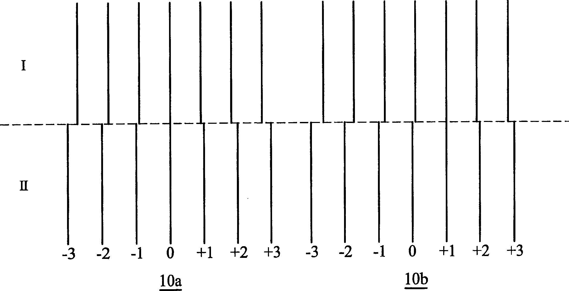
[0045] Figure 1a is a schematic diagram of inkjet image skew detection, where 10a It is the graphic printed by the inkjet head after receiving a test print data under normal circumstances, and 10b It is the graph printed after receiving a test print data under the condition that the inkjet head is skewed. exist Figure 1a Among them, area I is the printing situation where the inkjet head does not receive any displacement correction, and area II is the printing after the inkjet head receives different displacements in the rightward or leftward displacement direction and does not receive any displacement. result. In this figure, the inkjet head receives one, two, and three d...


PUM


Abstract

The present invention relates to an ink gun printing correction device and its printing correction method. Said method includes the following steps: detecting skew direction of said ink gun, receiving several line data, every line data is correspondent to jet nozzles of every line on said ink gun from top to bottom, dividing every said line data into N zones from top to bottom, printing and correcting continuous N line data in said line data and transferring the corrected line data to ink gun to print said corrected line data.

Description

technical field [0001] The present invention is an invention related to an inkjet head, in particular to a printing correction method and device for an inkjet head. Background technique [0002] After an inkjet printer has been used for a period of time, it may be found that the printed data will be skewed. Therefore, it is necessary to use a printing correction method or device to improve this situation. With the current design of printers, the ink cartridge and the inkjet head are mostly combined. Consumers can also replace the inkjet head every time the ink cartridge is replaced to avoid inkjet head clogging. Theoretically, when the inkjet head is inserted into the printer, the inkjet head should be perpendicular to the print bar of the printer, but it may be due to the error of the printer itself or the error caused by the user placing the inkjet head into the printer , so that the inkjet head and the printing transmission shaft have an inclined angle, causing the graph...

Claims


Application Information

Patent Timeline
IPC IPC(8): B41J2/135B41J29/393
Inventor 欧享沛黄介一
Owner IND TECH RES INST
Learn More