Device for transmitting the movement to fans, in particular of vehicles

A fan and motion technology, applied to the fan, can solve the problem of difficult arrangement of the driver's cab

Inactive Publication Date: 2010-06-16
BARUFFALDI
View PDF7 Cites 0 Cited by
  • Summary
  • Abstract
  • Description
  • Claims
  • Application Information

AI Technical Summary

Problems solved by technology

[0012] However, evaluation of vehicles, especially heavy-duty trucks, etc., is done in such a way that cabs are preferably designed so that they are arranged as close to the ground as possible in order to reduce friction and improve the air permeability of the vehicle; however, the cab This arrangement of the is made difficult by the fan problem created above

Method used


Image

  • Device for transmitting the movement to fans, in particular of vehicles
  • Device for transmitting the movement to fans, in particular of vehicles
  • Device for transmitting the movement to fans, in particular of vehicles

Examples


Embodiment Construction

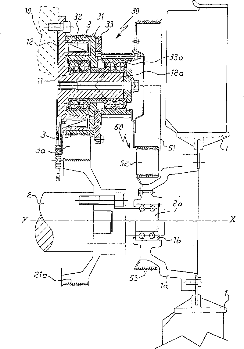
[0024] Such as figure 1 As shown, the cooling fan 1 is tightly constrained to a supporting bell-shaped member 1a arranged on a bearing 1b mounted on an extension 2a of a propeller shaft 2 of the vehicle so as to be connected thereto. The axes of rotation are coaxial.

[0025] On the same extension 2a of the transmission shaft 2, a first transmission pulley 21a is also installed, said first transmission pulley 21a is connected to a second pulley 3 by a belt 3a, the second pulley 3 is combined in more detail below The clutch rotor 31 is illustrated.

[0026] For ease of description, the following "longitudinal direction X-X" will be understood to mean the direction coincident with the longitudinal axis of the propeller shaft.

[0027] In more detail, the aforementioned rotor 31 is mounted on a bearing 11 keyed to a longitudinal hollow sleeve 12a of a fixed support flange 12, which is in contact with the bottom wall 10 of the engine. Integrates and forms the rotating element o...


PUM


Abstract

Device for transmitting the movement to a fan (1) for cooling the cooling fluid in a motor vehicle, mounted, by means of an idle support (1a,2001a), on an axis parallel to the longitudinal axis (X-X)of the driving shaft (2) of the vehicle, said device comprising movement generating means (2,2a) which are coaxial and integral with the driving shaft (2); means (21a;3a;22a,3b) for transmitting the movement of the driving shaft to a first clutch (30;230;330;430;530;2030;2230); at least one first friction clutch (30;230;330;430;530;2030;2230) with an electromagnetic actuating system, which is arranged on an axis parallel to the longitudinal axis (X-X) of the driving shaft (2) and the rotor (31) of which is connected to said movement transmission means (21a;3a;22a,3b) and the engagement of which produces a rotation of the fan (1) at a number of revolutions at least equal to that of the movement generating means (2,2a).

Description

technical field [0001] The invention relates to a device for transmitting motion to a fan for cooling coolant in a vehicle, said device being arranged on an axis parallel to its transmission shaft. Background technique [0002] In the technical field concerned with the cooling of coolant in motor vehicle radiators, it is known to force air onto the radiator in order to dissipate the heat in the liquid more quickly to the outside, said forced air flow being obtained by rotating a fan, The above-mentioned fan is usually mounted on the water pump shaft or on the transmission shaft or on a driven and fixed shaft with a pulley receiving the motion from a belt driven by the transmission shaft. [0003] It is also known that the above-mentioned fan must be made to rotate only when a certain predetermined water temperature is reached, and the above-mentioned water temperature is detected by a temperature control switch, which activates an electromagnetic clutch, and the closure of t...

Claims


Application Information

Patent Timeline
Patent Type & Authority Patents(China)
IPC IPC(8): F01P7/08
Inventor P·博菲里C·贝罗蒂E·德波利F·纳塔里M·特科
Owner BARUFFALDI
Why Eureka
Try Eureka