Method and devices for designing defensive appliance

A technology for designing methods and equipment, applied in the directions of gas injection devices, gas injection devices, offensive equipment, etc.

Inactive Publication Date: 2006-07-05
马水旺
View PDF0 Cites 0 Cited by
  • Summary
  • Abstract
  • Description
  • Claims
  • Application Information

AI Technical Summary

Problems solved by technology

[0003] The purpose of the present invention is to provide a design method and device of a defense device, which can solve the problems of trauma caused by a hard stick hitting the human body and safe and reliable opening and closing of the safety device, and its use is safer and more reliable

Method used


Image

  • Method and devices for designing defensive appliance
  • Method and devices for designing defensive appliance

Examples


Embodiment 1

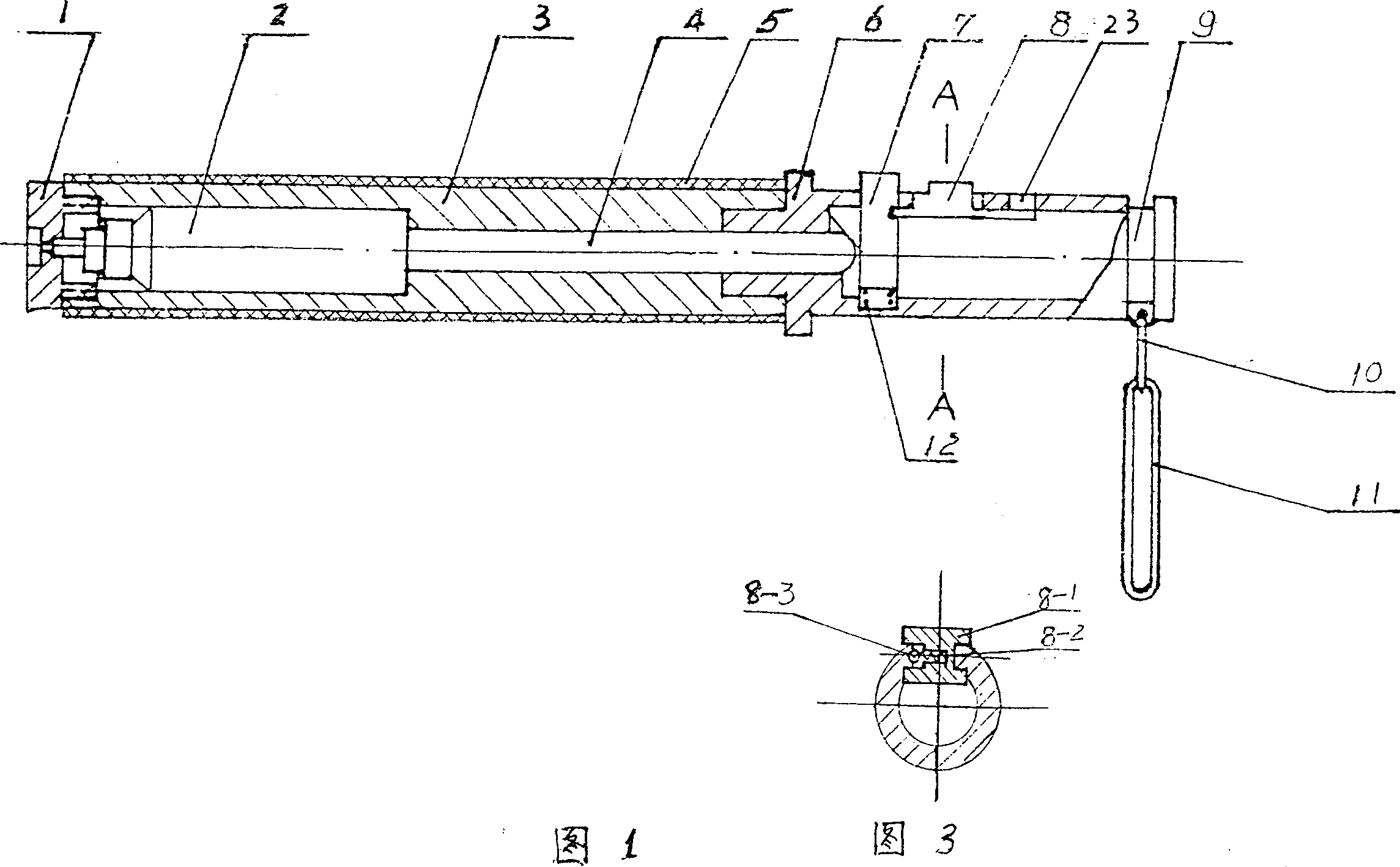
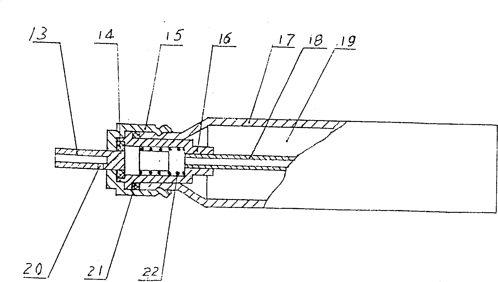
[0018] Embodiment 1 as shown in Figure 1: this stick type injection device is that the injection pipe 2 that stimulates is installed in a circular injection tube 3, and injection pipe 2 is made of injection mechanism, pipe body 17, fixed cover 15, sealing ring 21 1. Gasket 14 is connected, the injection mechanism is set in the mouth of the pipe body 17, the sealing ring 21 is set on the injection mechanism and pressed on the end surface of the mouth of the pipe body 17 through the fixed cover 15, and the gasket 14 is set on the injection rod 13 Use the fixed cover 15 to press fit in the groove at the mouth end of the spray rod seat 16. The spray mechanism is composed of the spray rod 13, the gasket 14, the spray rod seat 16, the spring 22, and the guide tube 18. There is a spring 22 in the spray rod seat. The outlet end is equipped with a spray rod 13 inside, and the spray rod 13 is sleeved on the gasket 14, and there is a small hole 20 on its side so that the small hole 20 can...


PUM


Abstract

A defense device of stick type is a stick type of jetting device for jetting out irritant aerial fog or irritant jet-flow. It is featured as applying elastic layer as external surface of jet cylinder, placing jet tube in jet cylinder, connecting seal head at front end of jet cylinder, setting a propelling mechanism at back of jet cylinder, packing irritant with pressure in jet tube, setting handle at back of jet cylinder and laying switch as well as safety mechanism on handle.

Description

Technical field [0001] The invention belongs to a design method and device of a public safety defense product, in particular to a design method and device of a stick type defense device for spraying an aerosol or liquid jet stimulant. Background technique [0002] In the prior art, the equipment used for public security or armed police's close-range explosion-proof self-defense is mainly a baton, which can only be hit or electric shock at close range, but such as a mace, telescopic steel rod, and hard plastic batons are likely to cause damage to the human body. Bleeding wounds, electric shocks are also disabled as unsafe. Though baton formula self-defense device comes out at present, because of its stick body material is made of hard material, hitting can cause obvious trauma to human body, and this also is not allowed at present civilized law enforcement. Contents of the invention [0003] The purpose of the present inven...

Claims


Application Information

Patent Timeline
IPC IPC(8): F41H9/04F41B9/00
CPCF41B9/0087
Inventor 马水旺
Owner 马水旺
Why Eureka
Try Eureka