Balancing set for optical disk in optical disk driver

A technology of optical disc drive and balancing device, which is applied in the direction of instrument, recording information storage, etc., can solve the problems of reducing insertion force, disc rotation insertion, left/right outer diameter difference, etc., and achieves the effect of alleviating noise and preventing rotation.

Inactive Publication Date: 2006-07-05
LEJIN GUANGDIAN ELECTRONIC CO LTD SHANGHAI
View PDF0 Cites 0 Cited by
  • Summary
  • Abstract
  • Description
  • Claims
  • Application Information

AI Technical Summary

Problems solved by technology

[0007] However, if figure 2 As shown, when the optical disc 10 is inserted, due to the difference in balance, there may be problems in the transfer path and loading action of the optical disc 10
[0008] In other words, since the left / right side of the roller outer diameter (R1) is not fixed, that is, when the rubber material roller 30 is used for a long time, since wear can occur, a difference occurs in the left / right side outer diameter, and disc transfer is not smooth. able to accurately
[0009] Moreover, since the heights of the left / right sides (H1, H2) of the disc guide 20 provided on the loading substrate 40 also differ in height
That is, even if the difference in height between the left and right sides of the disc guide 20 is only about 0.1mm, there is a problem that the disc is rotated and inserted or the insertion force is lowered during loading.

Method used


Image

  • Balancing set for optical disk in optical disk driver
  • Balancing set for optical disk in optical disk driver
  • Balancing set for optical disk in optical disk driver

Examples


Embodiment Construction

[0035] The implementation of the optical disc balancing device of the optical disc drive of the present invention will be described in detail below with reference to the accompanying drawings.

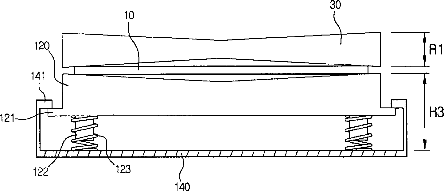
[0036] image 3 It is a side sectional view of an embodiment of the disc balancing device of the disc drive of the present invention. Figure 4 It is an exploded oblique view of the back surface of the disc guide part and the elastic tool of the disc balancing device of the disc drive of the present invention. Figure 5 It is a combination state diagram of the back surface of the disc guide part and the elastic tool of the disc balancing device of the disc drive of the present invention.

[0037] refer to image 3 , we can see that the optical disc balancing device of the optical disc drive is composed of the following parts: the optical disc guide 120 keeping a certain distance from the loading substrate 140; An elastic tool 123 provided between the disc guide 120 and the loading s...


PUM


Abstract

The invention relates to a CD balancing device for a CD-ROM, comprising the parts: a loading substrate; a CD guiding part on the substrate; roller on the upper part of the CD guiding part; elastic tool, providing specific bounce for keeping CD balanced between the CD guiding part and the roller and able to reduce the space between them. The invention can prevent the moving CD from rotating so as to achieve the effect of reducing noises caused by the space.

Description

(1) Technical field [0001] The present invention relates to an optical disc drive, in particular to a disc balancing device for an optical disc drive that can automatically maintain disc balancing when a disc is inserted. (2) Background technology [0002] In general, methods for transferring an optical disk in an optical disk drive can be classified into a tray method, a finger method, and a roller method. Among them, the tray method refers to the method of placing the disc on the tray formed on the contact surface of the disc to move and transfer the disc; the finger method refers to the method of holding the edge of the disc with fingers to transfer the disc; the roller method is used as a roller. When it is in close contact with the surface of the disc, the friction between the two is used to transfer the disc. [0003] The optical disk drive of the above-mentioned roller transfer method is composed of the following parts: a roller driving part that transfers the optica...

Claims


Application Information

Patent Timeline
IPC IPC(8): G11B17/04
Inventor 安用模
Owner LEJIN GUANGDIAN ELECTRONIC CO LTD SHANGHAI
Why Eureka
Try Eureka