Supercharge Your Innovation With Domain-Expert AI Agents!

Drilling apparatus

一种钻井、设备的技术,应用在改进的钻井设备领域,能够解决笨重等问题

Inactive Publication Date: 2006-07-05
阿兰・L・纳克鲁德
View PDF0 Cites 0 Cited by
  • Summary
  • Abstract
  • Description
  • Claims
  • Application Information

AI Technical Summary

Problems solved by technology

Although the hoses prevent leakage between the drill string and the blades, they are rather bulky, in order to freely pivot movement from a vertical position to a horizontal position at the end of the drill string, after repeated use and impose restrictions on the mounting blades. ability to suffer wear and tear (blow out)

Method used


Image

  • Drilling apparatus
  • Drilling apparatus
  • Drilling apparatus

Examples


Embodiment Construction

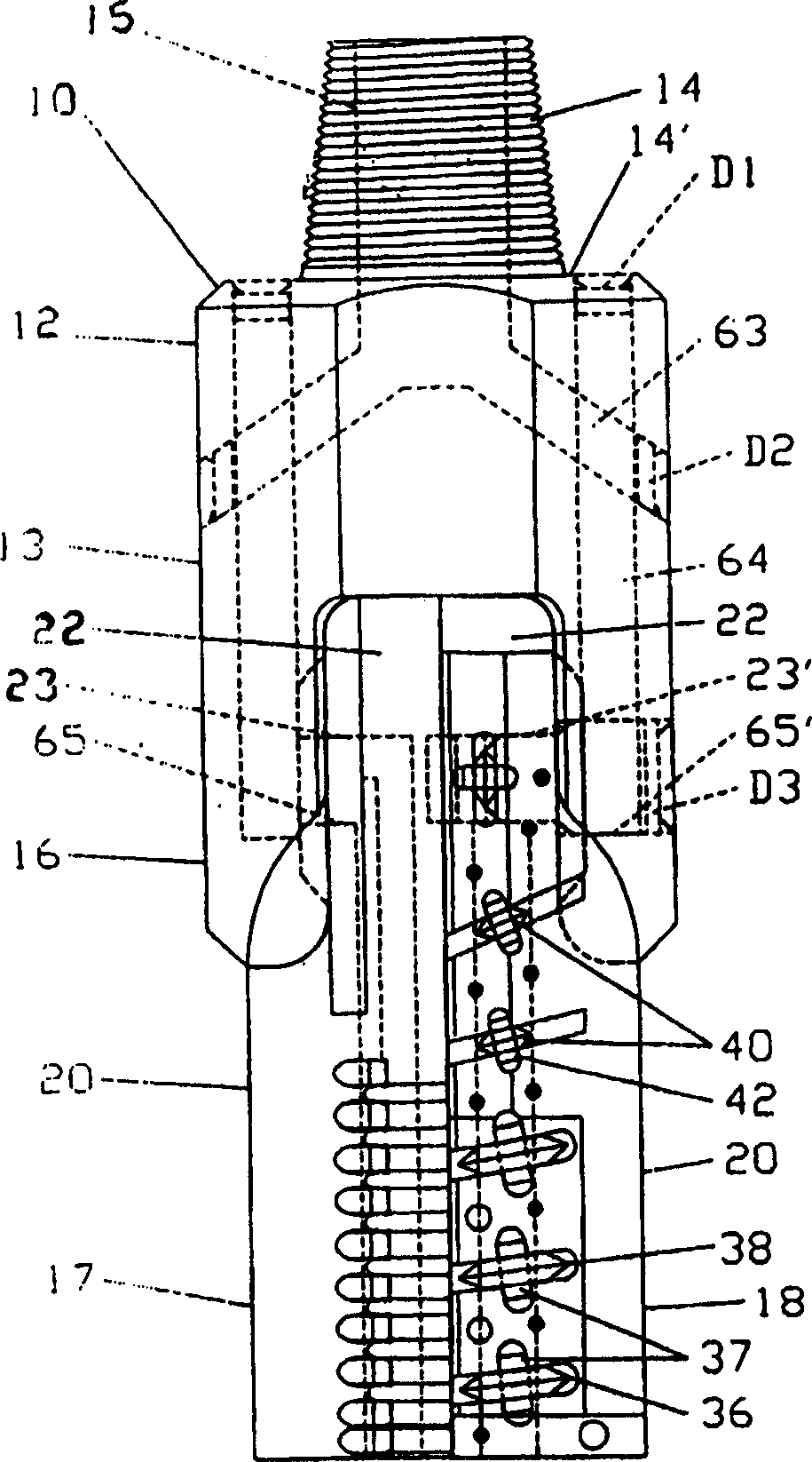
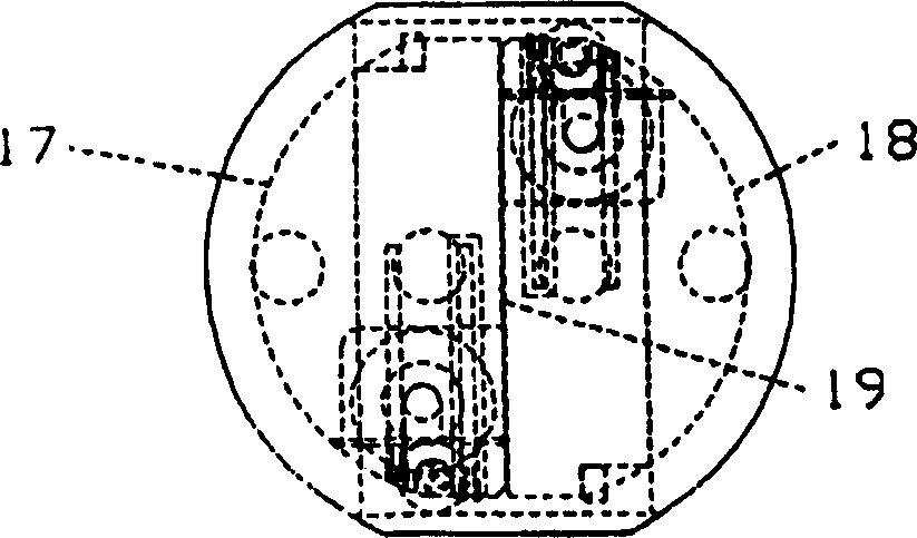
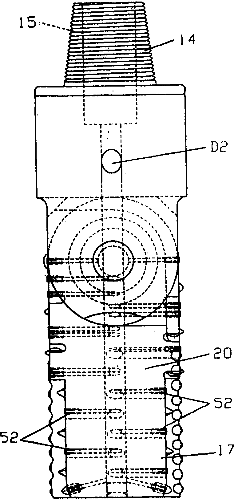
[0022] Refer to the accompanying drawings for details, Figure 1 to Figure 4 A drill bit assembly 10 is shown by way of example, comprising a sub 12 in the form of a hollow cylindrical blade support 13 having an upper threaded end 14 and a lower forked pivot end 16 . A pair of cutting blades 17 and 18 each consist of an elongated blade arm 20 tapering to a circular pivot end 22 having transverse holes 23, 23' for pivotal connection to the The lower pivoting end 16 of the blade support 13 . Each blade arm 20 is of generally semicircular configuration and has a flat facing surface portion 19 . Thus, the blades 17 and 18 are supported in a substantially longitudinally extending first position when at rest and when performing as figure 1 and Figure 4 The pivoting movement between the transverse and mutually perpendicular directions respectively during operation is shown. This pivot end 16 has the form of an ear or extension of a hollow cylinder, so that it is arcuate in secti...


PUM


Abstract

A drilling apparatus (10) for earth boring operations is of the type having cutter blades (17, 18) mounted on a support body (12, 72, 82) at the lower end of a drill string and includes a novel arrangement of fluid bore sections (15, 23, 23', 63, 64, 65', 92) for delivering fluid under pressure into fluid discharge passages (50, 52) in each of the blades and a bifurcated pivotal mounting portion (16, 74, 91) on the body which enables the bore sections to supply fluid to the cutter blades through a ball joint (22) on the pivotal axis. Modified forms of invention are specifically designed for cutter blades which are intended to perform reaming operations but include the fluid delivery system as well as an extended delivery system (86) for delivering fluid under pressure to other tools in the drill string.

Description

technical field [0001] The present invention relates to a drilling apparatus and, more particularly, to a novel and improved drilling apparatus having fluid supply holes for directing fluid from a drill string to drill bits, reaming tools, and the like. The invention is suitable for use with liquid and gaseous substances, but is particularly useful for use with liquids in subterranean formations. Background technique [0002] I have previously invented drill bit assemblies and reaming devices that feature a rotating drill bit mounted on the lower end of a conventional drill string and a cutting blade pivotally mounted to the drill bit. High speed ground drilling operations are performed with the aid of fluid, the cutting blades having fluid discharge nozzles in communication with fluid supply hoses extending down the drill string to directly connect with the fluid discharge passages of each cutting blade. Although the hoses prevent leakage between the drill string and the b...

Claims


Application Information

Patent Timeline
Patent Type & Authority Applications(China)
IPC IPC(8): E21B7/28E21B7/18E21B10/62E21BE21B10/32E21B10/34
CPCE21B10/345E21B10/32
Inventor 阿兰·L·纳克鲁德
Owner 阿兰・L・纳克鲁德
Features
  • R&D
  • Intellectual Property
  • Life Sciences
  • Materials
  • Tech Scout
  • Unparalleled Data Quality
  • Higher Quality Content
  • 60% Fewer Hallucinations
Learn More