
Cutter head for a meat cutter

A meat grinder and knife head technology, applied in the system field, can solve the problems of unhygienic knife head, etc., achieve the effect of simplifying transportation, simplifying logistics work, and avoiding abnormal work

Inactive Publication Date: 2010-09-01
CFS GERMANY
View PDF9 Cites 0 Cited by
  • Summary
  • Abstract
  • Description
  • Claims
  • Application Information

AI Technical Summary

Problems solved by technology

[0003] However, these cutter heads have the disadvantage that they can only be assembled in relatively complex situations, since the cutter head disc can generally only be assembled with the cutter on the cutter shaft
Additionally, the cutter heads are less hygienic as the material to be cut can collect within the cutter head disc and between the cutter head disc and the knives assembled thereon

Method used


Image

  • Cutter head for a meat cutter
  • Cutter head for a meat cutter
  • Cutter head for a meat cutter

Examples


Embodiment Construction

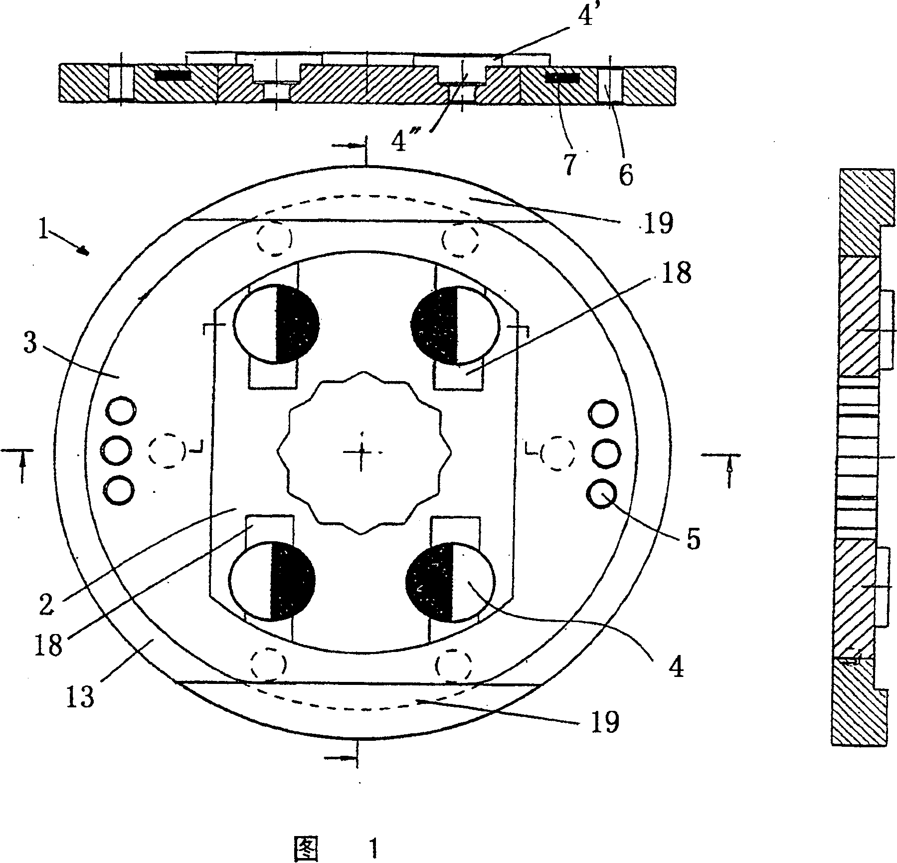
[0043] figure 1An embodiment of the cutter head disc 1 according to the invention is shown, comprising a metal core 2 and a plastic sheath 3 . According to the invention, the core 2 is encapsulated by a plastic sheath 3 by casting so that, without further provision, there is an interlocking and / or frictional engagement between the two parts and material cannot collect between the metal core and the plastic sheath. The exterior of the metal core is preferably provided with structures, such as ribs, which improve the bond between the core 2 and the plastic skin. It is preferred to mount a 12 edge socket for the bit drive shaft in the metal core. Also provided in the metal core are recesses 18 which in each case can accommodate an eccentric fixing bolt with which the knife (not shown) can be mounted on the cutter head disc . In the present case, the eccentric fixing bolt 4 is inserted into the groove 18 . Each eccentric fixing bolt has a disc-shaped head 4' mounted eccentric...


PUM


Abstract

The invention relates to a cutter head disk for a meat cutter, on which at least one knife can be mounted by means of eccentric bolts and optional magnets and which is provided with a metallic core for accommodating the drive shaft. Preferably, said core comprises a plastic envelope. The invention further relates to a knife having a geometry that is provided with a great axial load-bearing capacity. Also disclosed are a system comprising a cutter head disk and two knives, a cutter head encompassing several systems, and a method for assembling a cutter head.

Description

technical field [0001] The invention relates to a cutter head disc for a meat grinder, on which at least one knife can be mounted, and which preferably has a metal core for receiving a drive shaft. The invention also relates to a system comprising a cutter head disc and two knives, said cutter head comprising a plurality of systems, and a method for mounting cutter heads, and a cutter head. Background technique [0002] A general type of cutter head is known from the prior art. For example, patent publication US 3,491,818 discloses a knife for a meat grinder, said knife having a cutting head mounted on a shaft with a tapered shank. A bushing with an annular sleeve fits over the aforementioned tapered rod. The blades and the locking adjustment discs are alternately installed on the bushing, and the adjustment discs make the blades have the same axial distance from each other. To adjust the individual blades, several micrometric adjustment screws are utilized. The bit is f...

Claims


Application Information

Patent Timeline
IPC IPC(8): B26D1/00B26D7/26B26D7/08B02C18/20
CPCB02C18/20B26D7/08B26D7/2614Y10T83/9379
Inventor N·雅格比J·伯恩哈德特
Owner CFS GERMANY
Learn More