Power distribution system

A power distribution network and electric power technology, applied in information technology support systems, wind power generation, electrical components, etc., can solve problems such as unresolved production network balance

Inactive Publication Date: 2006-07-19
EC POWER LLC
View PDF3 Cites 4 Cited by
  • Summary
  • Abstract
  • Description
  • Claims
  • Application Information

AI Technical Summary

Problems solved by technology

Telematics can be used, but it does not solve the pro

Method used


Image

  • Power distribution system
  • Power distribution system
  • Power distribution system

Examples


Embodiment Construction

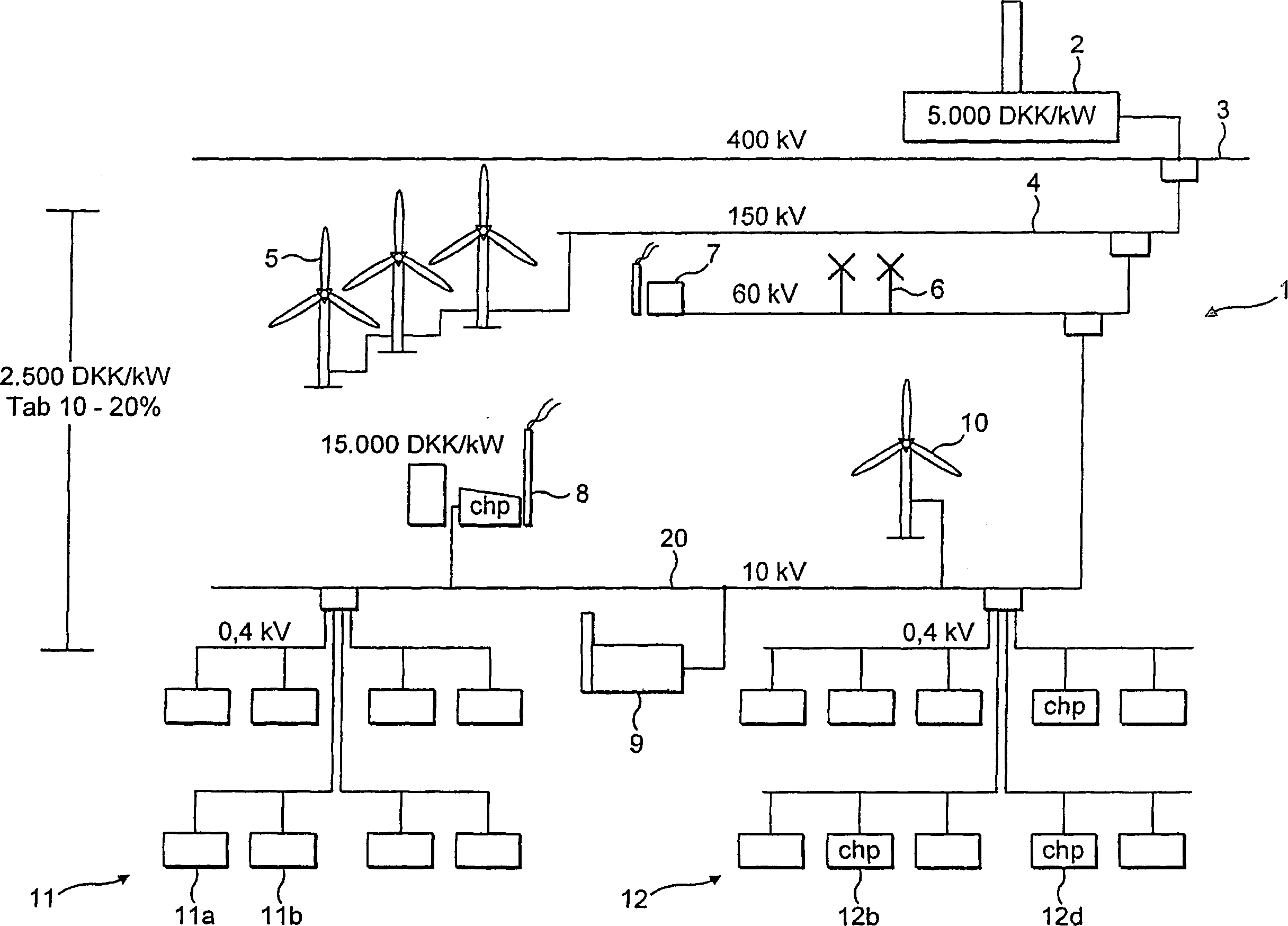
[0038] figure 1 Electricity generation network 1 showing the types used in Denmark. This is a marked difference from the networks established in some other countries where large power stations provide most of the production capacity. The largest scale generating capacity is provided by one or more conventional power plants 2 which supply the network 3 on the order of several gigawatts to 400 kilovolts. This network is used to send electricity over long distances. It is then converted to 150 kV and fed to the local network 4 . The network also has generating capacity such as large offshore wind turbines 5 connected to it.

[0039] Power from the 150 kV network is then converted to 60 kV supplied to the regional network. There may be inland wind turbines 6 and large district cogeneration units 7 connected to the network.

[0040] It is then down-converted to 10 kV to form a medium voltage supply network 20 for distribution to the various local areas. Small scale CHP units ...


PUM


Abstract

A local electricity distribution network (1) comprising a local transmission hub (13) and plurality of units (12a, 12b) arranged to selectively import and export electricity from and to the hub (13), the hub in turn being arranged to selectively import and export electricity from and to an external grid (20). The individual units (12a, 12b) decide if they are to export or import energy to or from the local transmission hub (13) based on information relating to the energy market received from the local hub. In the same way the local hub decides if it is to export or import energy to or from the external grid (20) based on energy market information received from the external grid.

Description

technical field [0001] The present invention relates to power distribution systems and in particular to systems arranged to maintain a balance between the generation and consumption of electricity while ensuring that electricity is produced in an efficient manner. It also relates to a local electricity distribution network for forming part of the system, and to a power generating unit for forming part of the network. Background technique [0002] In the UK there are mainly large power stations, while only relatively small amounts of electricity are generated by lower output units such as windmills, small scale combined heat and power units (CHP). The power station is connected to the national high-voltage transmission grid, which enables electricity to be distributed throughout the country on demand. Thus, while it generally does not store energy (pumped hydro is a very exception), it acts in a way as a large reservoir of power. To balance supply and demand, the grid opera...

Claims


Application Information

Patent Timeline
IPC IPC(8): H02J3/00F03D7/04
CPCY02E10/723F05B2240/96F03D7/0284H02J3/008Y04S50/10Y02E10/72Y02P80/14H02J3/06H02J3/00
Inventor 比贾恩·博格纳索伦·S·阿比尔德加德詹斯-奥托·R·安德森
Owner EC POWER LLC
Why Eureka
Try Eureka